
Heat exchanger with highly flexible use

a heat exchanger and flexible technology, applied in the direction of energy-efficient heating/cooling, sustainable buildings, stationary tubular conduit assemblies, etc., can solve the problems of increased dimensions, increased size, and increased size, and achieves the greatest assurance of reliability and safety in use, high flexibility, and high flexibility.

Inactive Publication Date: 2012-07-19
UNIVERSITY OF CALABRIA
View PDF7 Cites 3 Cited by
  • Summary
  • Abstract
  • Description
  • Claims
  • Application Information

AI Technical Summary

Benefits of technology

[0015]The aim of the present invention is to provide a heat exchanger with highly flexible use which solves and overcomes, respectively, the above mentioned drawbacks and limitations of conventional heat exchangers.
[0016]Within this aim, an object of the present invention is to provide a heat exchanger with highly flexible use which, thanks to its particular constructive characteristics, is capable of giving the greatest assurances of reliability and safety in use.

Problems solved by technology

This last solution is such as to further increase the thermal efficiency of the exchanger but suffers the drawback that, in order to provide the hollow pins, such pins must have a large cross-section so as to allow circulation of the fluid to be heated inside them.
This fact leads to an increase in the dimensions of the voids between one pin and the next, thus allowing the combustion gases to pass through the heat exchange chamber without adequately flowing over the pins that are present inside it.
In practice, this increase in size does not allow optimum utilization of the heat of the combustion gases that circulate in the heat exchanger.
More specifically, this drawback is felt even more strongly when it is not possible to achieve economies of scale during manufacture, i.e., when the number of heat exchangers to be manufactured is limited to a few units and, especially, when the design specifications have particular nonstandard requirements.
Another drawback of conventional exchangers consists in that, since they are generally provided by means of a monolithic structure obtained by casting, the provision of the internal hollow pins is an operation which is difficult and expensive to perform.

Method used


Image

  • Heat exchanger with highly flexible use
  • Heat exchanger with highly flexible use
  • Heat exchanger with highly flexible use

Examples


first embodiment

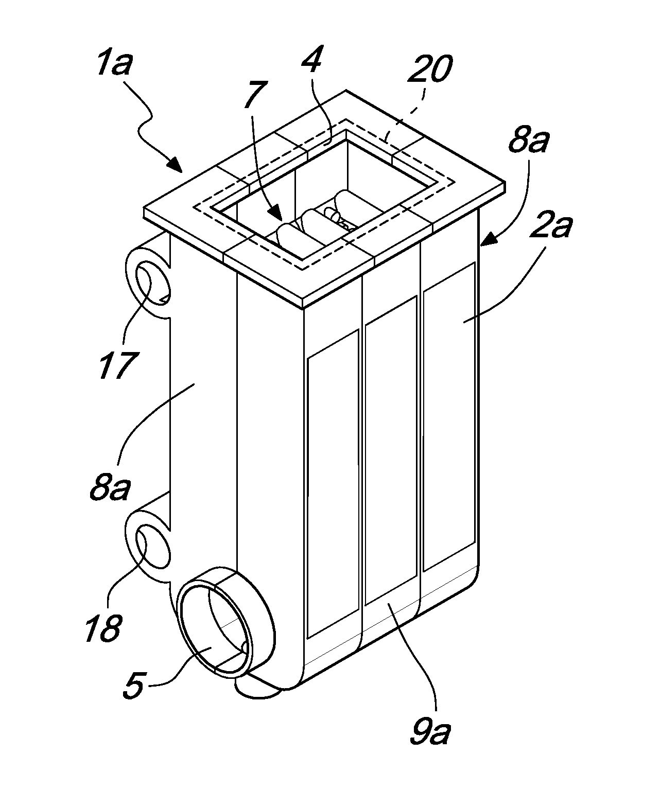
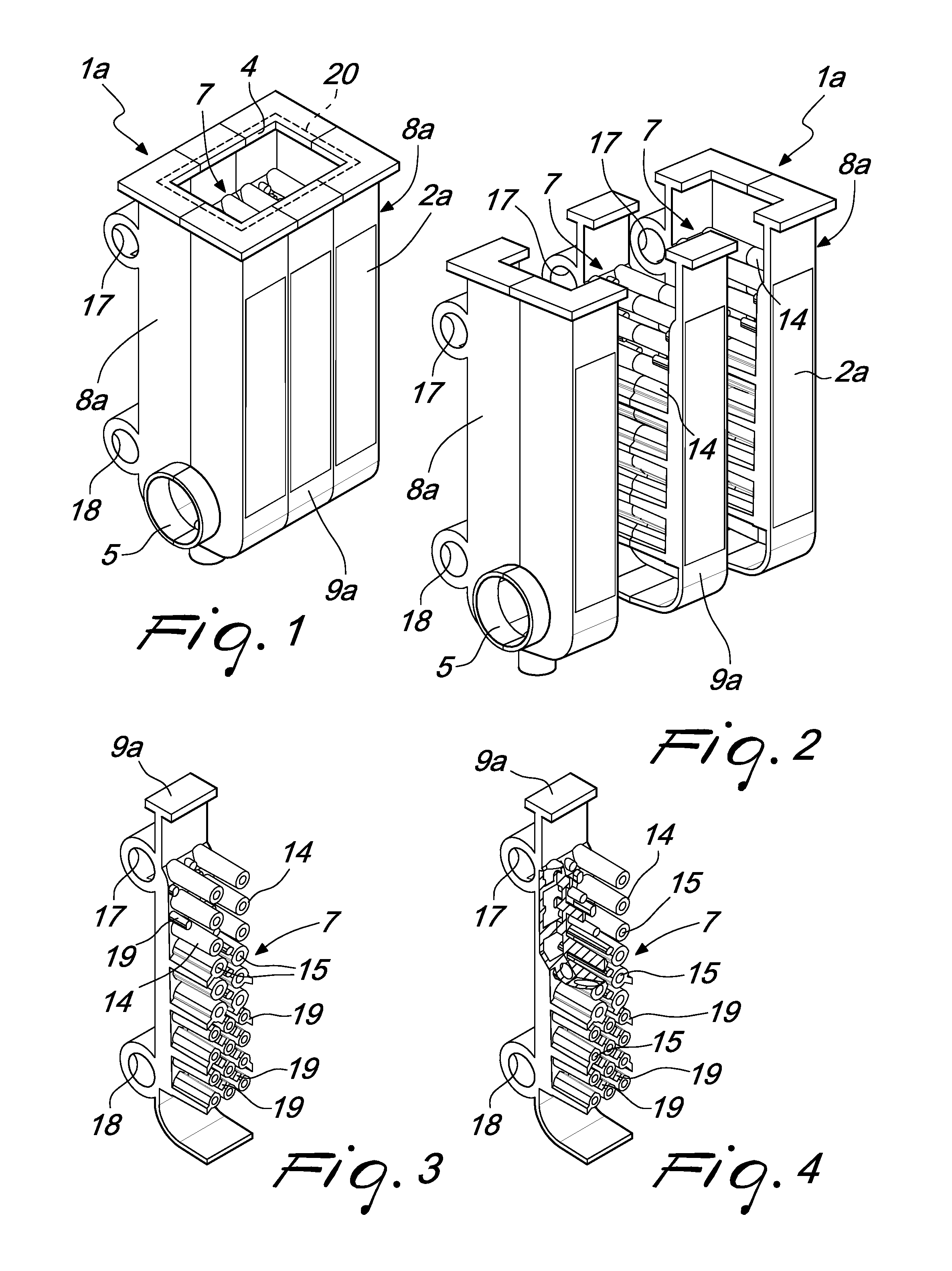
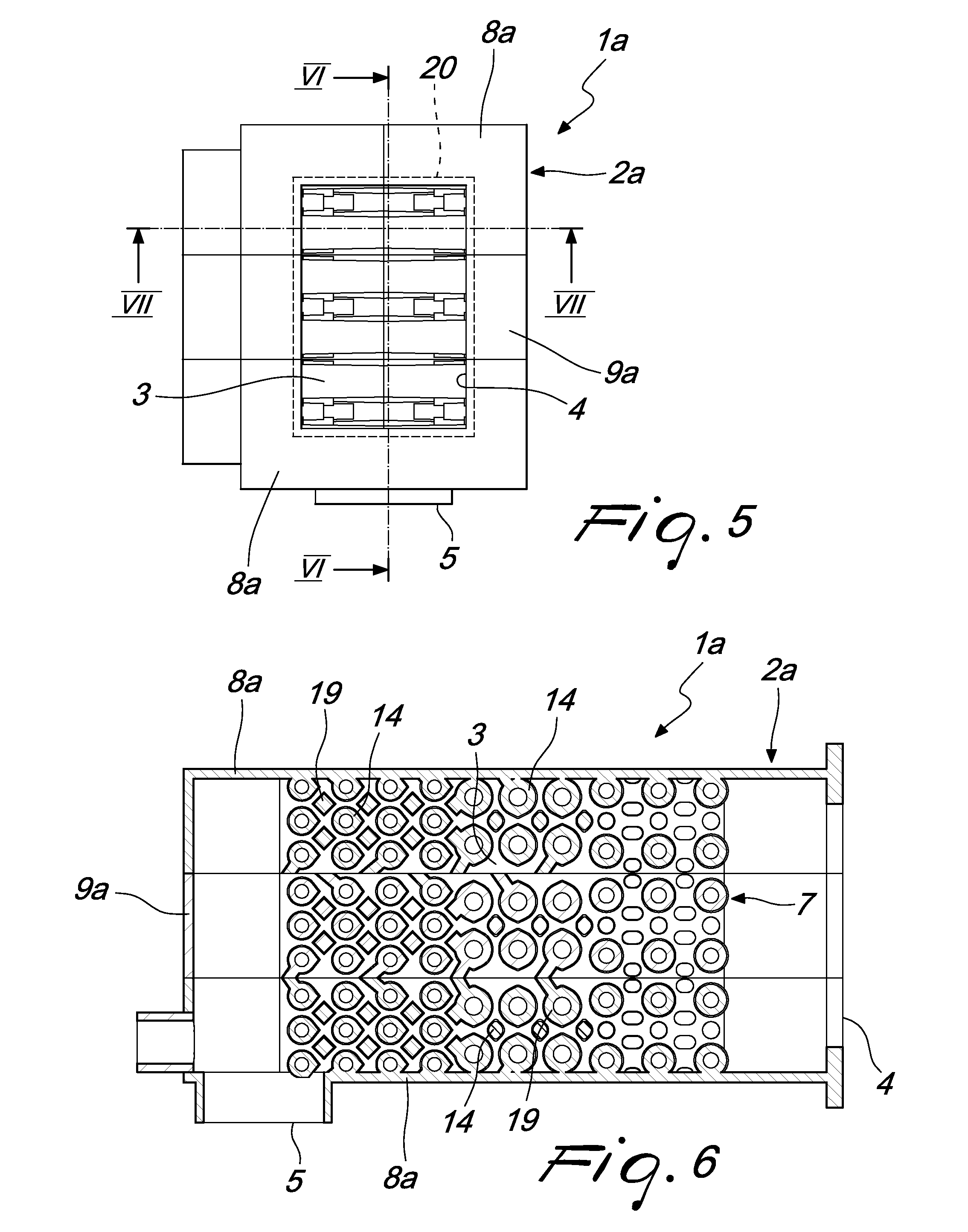
[0051]With reference to the first embodiment, the additional modular element 9a of the heat exchanger 1a does not have partitions, so as to define, with the modular end elements 8a, a single heat exchange chamber 3 with a single inlet 4 and a single evacuation duct which ends with the outlet 5.

second embodiment

[0052]Differently, in the second embodiment each additional modular element 9b of the heat exchanger 1b has a partition 10 which is such as to divide the inner volume of the heat exchanger 1b into a plurality of heat exchange chambers 3, one for each pair of modular elements.

[0053]More specifically, in this embodiment each heat exchange chamber 3 is independent of the other heat exchange chambers 3, it being delimited laterally by a pair of modular elements, and has a dedicated inlet 4. Despite this, the heat exchange chambers 3 are connected to a single evacuation duct which ends with the outlet 5.

third embodiment

[0054]With reference to the third embodiment, shown in FIGS. 16 to 19, the heat exchanger 1c in its minimum configuration can comprise a single modular end element 8c with a closed profile, which is provided in a monolithic structure and delimits inside it a first heat exchange chamber 3 which is provided with a single inlet 4 and with a single outlet 5.

[0055]Advantageously, in this embodiment, in order to increase the thermal power that can be exchanged by the heat exchanger 1c, one or more additional modular elements 9c are provided which can be mutually associated laterally with the modular end element 8c or with another additional modular element 9c along at least one first plane which is substantially parallel to the vertical direction.

[0056]Each additional modular element 9c has an open profile with a face 34 which is open in order to delimit inside it a second heat exchange chamber 23 and in order to define a dedicated inlet 4 when associated with the modular end element 8c o...


PUM


Abstract

A heat exchanger, comprising a box-like body which delimits inside it at least one heat exchange chamber and has at least one inlet and at least one outlet for the passage through the chamber of combustion products along a preferred path. The box-like body defines at least partly in its side walls at least one duct for feeding a fluid and inside the heat exchange chamber elements are provided and are associated with the supply duct in order to increase the thermal efficiency of the heat exchanger. The heat exchanger comprises a plurality of distinct modular elements which are mutually to interconnected in order to define the box-like body. Each modular element may comprise at least one portion of the heat exchange elements, of the supply duct and of the chamber.

Description

[0001]This application claims priority from European Patent Application No. 11425007, filed Jan. 17, 2011, which is incorporated herein by reference.FIELD OF THE INVENTION[0002]The present invention relates to a heat exchanger with highly flexible use.BACKGROUND OF THE INVENTION[0003]Nowadays heat exchangers are known which are adopted in boilers designed to heat a fluid which is generally constituted by water or diathermic oil.[0004]Such heat exchangers are generally constituted by a monolithic box-like structure which is often made of aluminum and is such as to define inside it at least one heat exchange chamber that can be crossed by hot combustion gases.[0005]The duct for feeding the fluid to be heated, which by convection and conduction absorbs the heat carried by the combustion gases, is provided in the side walls of such box-like structure.[0006]In order to improve the thermal efficiency of such heat exchangers, it is known to provide inside the heat exchange chamber a plural...

Claims


Application Information

Patent Timeline
Patent Type & Authority Applications(United States)
IPC IPC(8): F28F9/02
CPCF28D7/1615F28F7/02F24D2220/06Y02B30/108F24H1/46F28F2255/14F24H1/32F28F3/022F28F2215/06Y02B30/00
Inventor ANGIOLINI, GIAN-LUCA
Owner UNIVERSITY OF CALABRIA
Learn More