Fuse state indicator

a state indicator and fuse technology, applied in the field of fuse state indicators, can solve the problems of difficult to see the backing layer beneath the combustible substance, difficult to reliably establish the electrical connection, and difficult to accurately orient the secondary fuse link with respect to the combustible substance,

Active Publication Date: 2008-05-06
EATON INTELLIGENT POWER LTD
View PDF35 Cites 18 Cited by
  • Summary
  • Abstract
  • Description
  • Claims
  • Application Information

AI Technical Summary

Problems solved by technology

The fuse state indicator of the '996 patent, however, is designed for use with a rectangular fuse module, and implementing such an indicator in other types of fuses presents a number of issues.
Reliably establishing the electrical connection and properly orienting the secondary fuse link with respect to the combustible substance is difficult.
Also, due to the curvature of the fuse body, the backing layer beneath the combustible substance can be difficult to see when the combustible substance is consumed.
In other types of fuses not having end caps, such as knife blade fuses having end bell assemblies, establishing a secure mechanical and electrical connection between the secondary fuse link of the indicator and the end bell assemblies with known clips and terminations is problematic.
Relative movement between the end bell assemblies and the indicator as the end bells are installed can damage or break the electrical connections to the indicator.
While soldered connections and adhesive backing materials may have some success in establishing electrical connections to the end bells, they do so at an increased cost.

Method used


Image

  • Fuse state indicator
  • Fuse state indicator
  • Fuse state indicator

Examples


Embodiment Construction

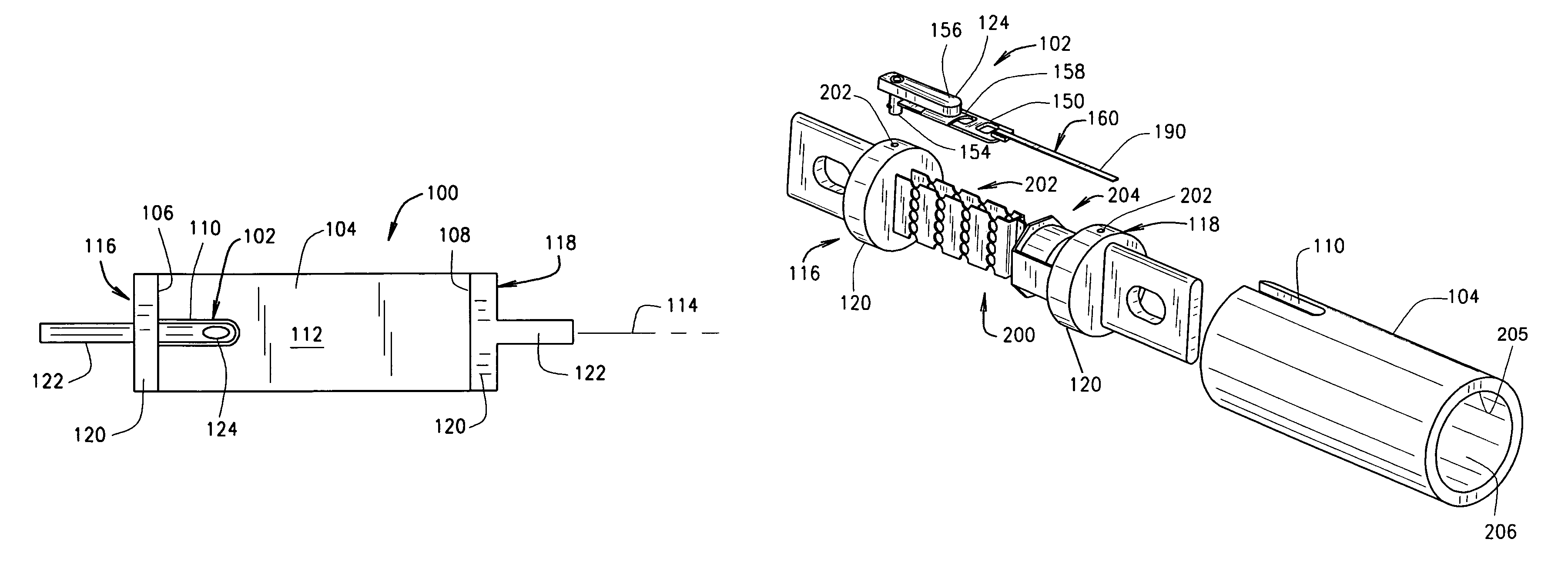
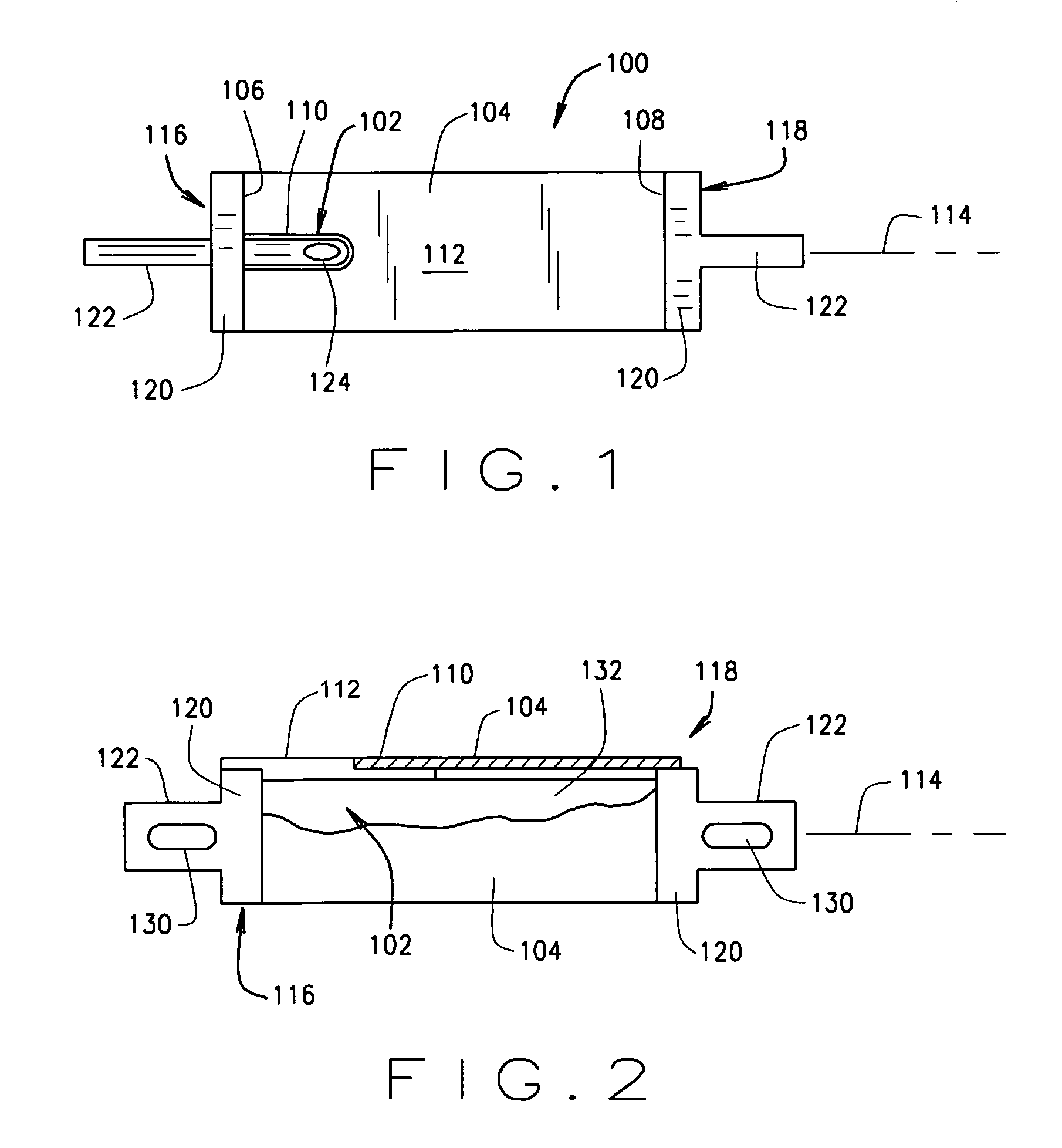
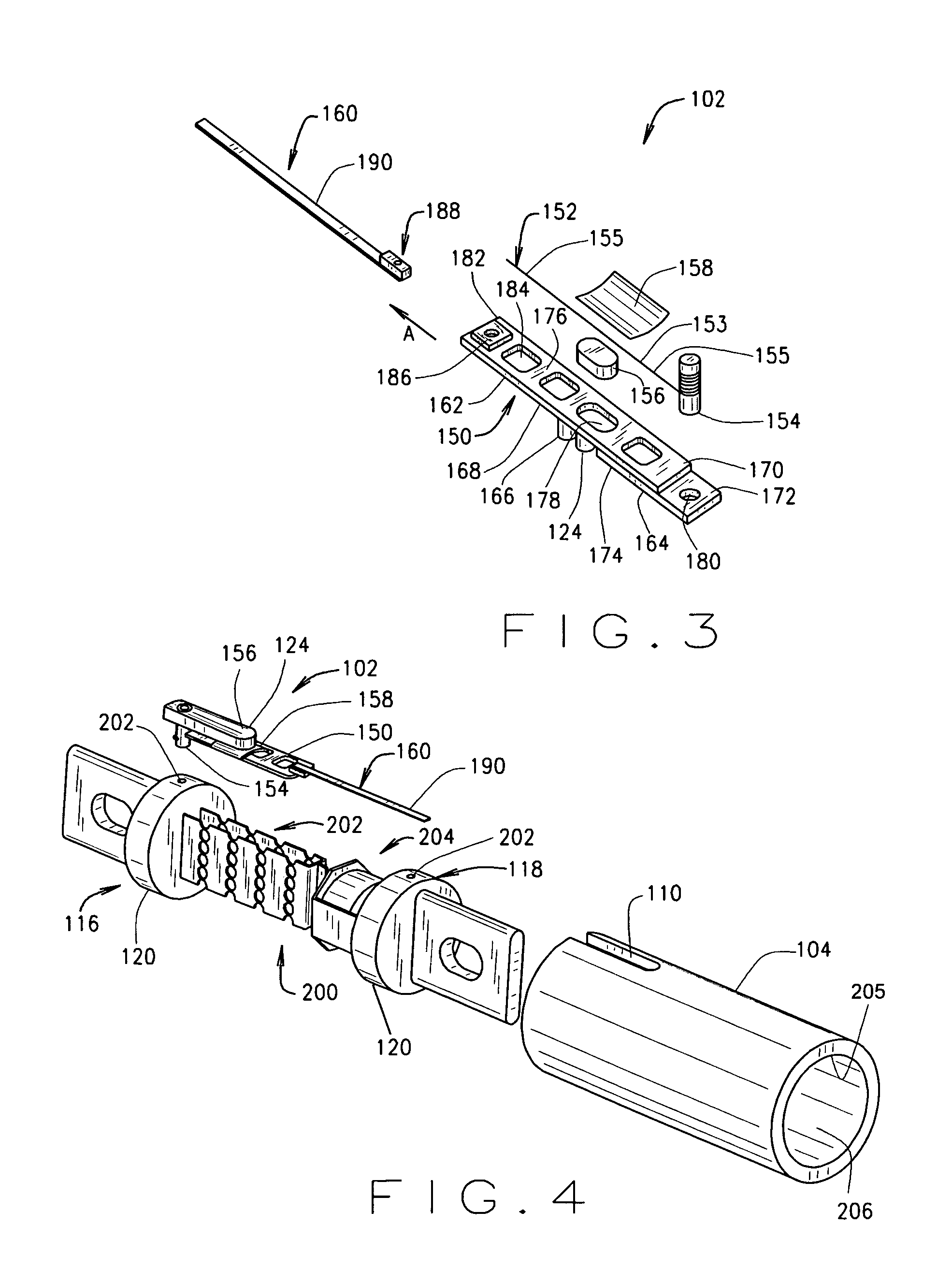
[0016]FIG. 1 is a top plan view of an exemplary fuse 100 including a fuse state indicator assembly 102 which, for the reasons set forth below, may be reliably mechanically and electrically connected to the fuse in a low cost and straightforward manner. In an exemplary embodiment, the fuse 100 includes a cylindrical fuse tube or body 104 fabricated from an insulative (i.e., nonconductive) material and having a first end 106, a second end 108 and a bore (not shown in FIG. 1) extending therebetween which houses a primary fuse element assembly (not shown in FIG. 1). An elongated slot 110 is formed in the body 104, and a portion of the indicator assembly 102 is located in the slot 110 on an outer surface 112 of the body 104. In one embodiment, the slot 110 extends from the first end 106 of the body 104 toward the second end 108 for a predetermined distance, and the slot 110 extends in a direction generally parallel to a longitudinal axis 114 of the fuse 100.

[0017]Conductive terminal elem...


PUM


Abstract

A fuse state indicator includes an extension member, a secondary fuse link coupled to the extension member, and a contact pin configured to engage a first terminal element of a fuse. An end of the secondary fuse link is wrapped around the pin and establishes an electrical connection thereto.

Description

CROSS REFERENCE TO RELATED APPLICATIONS[0001]The subject matter of this application is related to commonly owned U.S. application Ser. No. 09 / 537,518 filed Mar. 29, 2003, now issued U.S. Pat. No. 6,556,996, the disclosure of which is hereby incorporated by reference in its entirety, and is also related to the subject matter of commonly owned U.S. application Ser. No. 10 / 823,905, filed Apr. 14, 2004, the disclosure of which is hereby incorporated by reference in its entirety.BACKGROUND OF THE INVENTION[0002]This invention relates generally to fuses and, more particularly, to fuses with a fuse state indicator.[0003]Fuses are widely used as overcurrent protection devices to prevent costly damage to electrical circuits. Fuse end caps typically form an electrical connection between an electrical power source and an electrical component or a combination of components arranged in an electrical circuit. A fusible link is connected between the fuse end caps, so that when electrical current f...

Claims


Application Information

Patent Timeline
Patent Type & Authority Patents(United States)
IPC IPC(8): H01H85/30G01R31/07G08B21/18G08B23/00G01R31/74
CPCH01H85/30
Inventor DARR, MATTHEW R.
Owner EATON INTELLIGENT POWER LTD
Why Eureka
Try Eureka