System for testing tire sidewall irregularities and related methods

a tire sidewall and system technology, applied in the field of tire sidewall irregularity testing system, can solve the problems of affecting the safety of the end user, difficult to distinguish the sidewall from the bulge or depression, and significantly affecting the mechanical properties and thus the reliability of the tir

Active Publication Date: 2008-05-06
COMML TIME SHARING
View PDF9 Cites 11 Cited by
  • Summary
  • Abstract
  • Description
  • Claims
  • Application Information

AI Technical Summary

Problems solved by technology

Bulges and depressions are indicative of tire construction faults which can affect the safety of the end user.
The primary difficulty in the detection of such fault features lies in the fact that the areas under test include intentional sculptural features, such as raised relief-type letters, and acceptable process-related surface irregularities such as pin vents or mold flash that obscure the faults.
The acceptable surface features are of such a size that it is sometimes difficult to distinguish them from a bulge or depression.
As a result, simple threshold value decisions on the basis of measured form data does not lead to the clear distinction between fault features and acceptable surface features.
It will be appreciated that the manufacturer of the vehicle tire may find faults in the inner construction of the tire which significantly affect the mechanical properties and thus the reliability of the tire.
Construction faults show up as bulges or depressions on the exterior tire surface.
Although various methods have been developed to detect these bulges and depressions, they have been found to be lacking.
In particular, in view of the minimal difference between the size of bulges ranging about 0.012 inches in size, and the lettering of the tire ranging about 0.040 inches in size, it is still quite difficult to distinguish between the two and correctly designate a tire as having a bulge or depression in certain instances.

Method used


Image

  • System for testing tire sidewall irregularities and related methods
  • System for testing tire sidewall irregularities and related methods
  • System for testing tire sidewall irregularities and related methods

Examples


Embodiment Construction

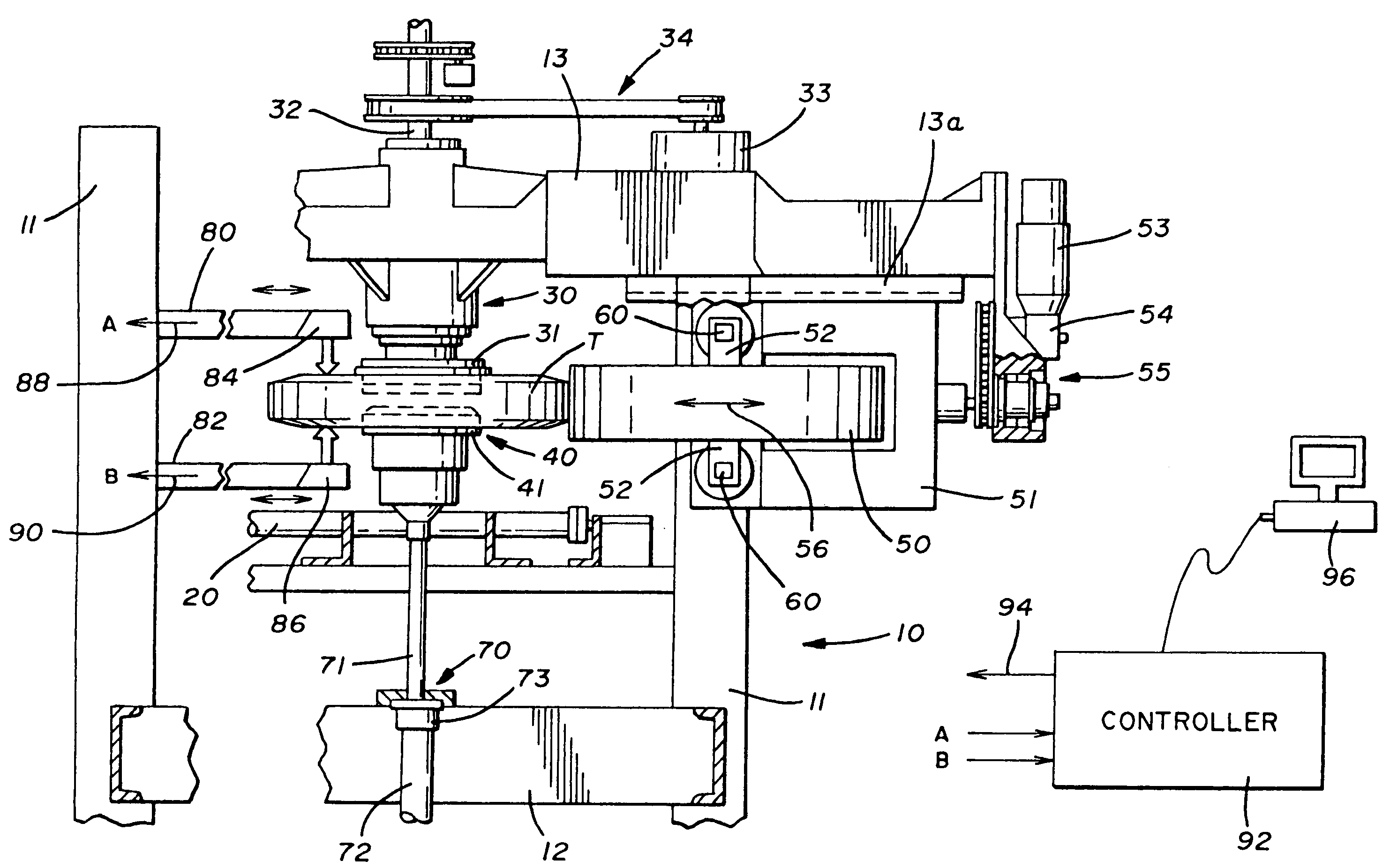
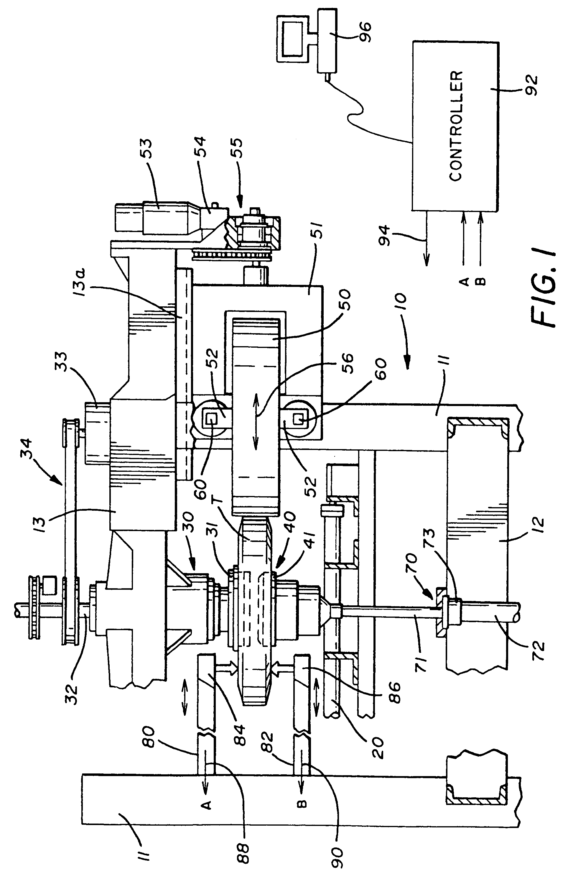
[0013]Referring first to FIG. 1 for a general description of the tire uniformity machine which is generally indicated by the numeral 10, it will be noted that vertical side frame members 11 and horizontal bottom and top frame members 12 and 13 form a framework for the machine, creating generally a box-like structure within which a tire, designated by the letter T, is received and tested. In that regard, the upper frame members 13 carry an upper chuck assembly 30 which includes a chuck 31 and a spindle 32 used to rotate the upper chuck assembly 30 during the testing operation. The spindle 32 of the upper chuck assembly 30 is driven by a motor 33 connected to the spindle by a belt or chain drive 34 for rotation purposes.

[0014]A lower chuck assembly 40, including a chuck 41, is mounted on lower frame members 12 and is supported on a shaft 71 which is attached to a hydraulic unit 70 which includes a piston 73 and cylinder 72 so that the lower chuck assembly can be elevated and lowered. ...


PUM


Abstract

A device for testing a tire that has a tread and extending sidewalls includes an apparatus for receiving and rotating a tire and at least one measurement device operatively placed to measure at least one of the sidewalls as the tire is rotated wherein the measurement device is radially moveable with respect to the sidewall in defined increments so as to obtain a measurement profile for each radial position. A controller is connected to the measurement device and receives each measurement profile, wherein the controller classifies the measurement profile into slope classifications, and wherein the controller monitors the slope classifications for defective patterns and, if detected, monitors a second measurement profile for another defective pattern. If another defective pattern is detected in the second measurement profile in the same radial region, the controller generates an indication that the tire is defective.

Description

TECHNICAL FIELD[0001]The present invention relates generally to tire testing equipment. In particular, the present invention relates to a testing device employed in the measurement of tire sidewalls as part of a production line test. Specifically, the present invention relates to tire testing equipment in that it uses a filtering process that ignores lettering and other acceptable process-related surface features on the sidewalls and detects bulges and depressions.BACKGROUND ART[0002]Tire uniformity machines and their use and function in the production and testing of vehicle tires are well-known in the art. One of the more important tests in this regard is the detection of so-called bulges, or depressions on the tire sidewalls. Bulges and depressions are indicative of tire construction faults which can affect the safety of the end user. The primary difficulty in the detection of such fault features lies in the fact that the areas under test include intentional sculptural features, s...

Claims


Application Information

Patent Timeline
Patent Type & Authority Patents(United States)
IPC IPC(8): G06F19/00G01B5/28
CPCG01M17/022
Inventor REYNOLDS, BRANDON M.ANENSON, TROY L.
Owner COMML TIME SHARING
Why Eureka
Try Eureka