Detonator system and method in connection with the same

a detonator and system technology, applied in the field of detonator systems, can solve the problems of affecting the work to be carried out, affecting the operation of the detonator system,

Inactive Publication Date: 2008-05-13
DETNET SOUTH AFRICA (PTY) LTD
View PDF15 Cites 18 Cited by
  • Summary
  • Abstract
  • Description
  • Claims
  • Application Information

AI Technical Summary

Benefits of technology

[0041]A major advantage of the present invention is that any arbitrarily selected operating device can be used together with any arbitrarily selected control unit, provided that these units have been associated with each other during a preceding presentation procedure as described above. Thus, it is possible on the one hand to make sure that only one operating device at a time is able to use the secure, wireless communication path connecting it to the control unit. On the other hand, any operating device can be associated with the control unit. As soon as an operating device is associated with a control unit, the previous association, if any, is rejected. Accordingly, the association is valid only for the units that were last linked to (associated with) each other.
[0042]Thus, a detonator system according to the invention comprises a control unit, such as a blasting machine, and a portable operating device. The control unit is adapted to control a plurality of detonators connected thereto. The detonators may be connected to the control unit by means of electrical wires (such as a bus) or a low-energy fuse wire or tube (such as NONEL™). The operating device is adapted to wirelessly transmit, at the request of an operator carrying the operating device, data containing, for example, an arm command or a fire command to the control unit.
[0043]It should be noted that nothing prevents other pieces of equipment from intercepting at least parts of the communication between the control unit and the operating device. This type of interception may be useful, for example, when assessing the function of the system or for statistical purposes.
[0044]To conclude, the present invention provides a detonator system comprising an operating device and a control unit, the system presenting, inter alia, the following features:
[0045]The operating device and the control unit are capable of communicating via radio signals in a secure manner. The control unit cannot be operated and monitored via radio signals from unauthorised radio transmitters, whether it is a non-specified operating device or control unit or any other radio transmitter.
[0046]The operating device and the control unit are designed in such manner that they are each exchangeable for equivalent units. During one firing, a control unit can be controlled from a first operating device, and during another firing, from a second operating device. It goes without saying that subsequent firings can be operated and monitored from one single operating device, but be carried out by different control units.

Problems solved by technology

One problem associated with detonator systems according to prior art is that the operator has to initiate firing from a site adjacent to the blast site to be able to physically press the arming and firing buttons of a blasting machine.
However, the detonator system of the above patent specification has a number of serious limitations and drawbacks.
It is evident that this will complicate the work to be carried out.
A further drawback of such a method is that the state of the detonators cannot be checked when the programming unit is disconnected.
Consequently, it is not possible to ensure, at a later stage, that the detonators are charged and that they will in fact detonate when receiving a fire command.
Moreover, a system according to the above patent specification is associated with considerable risks.
Any radio frequency interference in the receiver of a detonator, or any inadvertent transmission of a fire command from the transmitter, would therefore have devastating consequences.
Considering the fact that a round may comprise a considerable number of detonators, this may imply a significant increase in system costs.
Another general problem associated with wireless firing of detonators is that it is necessary to somehow ensure that only the intended round can be fired.
The obvious problem then is how to make sure that only the intended round is fired.

Method used


Image

  • Detonator system and method in connection with the same
  • Detonator system and method in connection with the same
  • Detonator system and method in connection with the same

Examples


Embodiment Construction

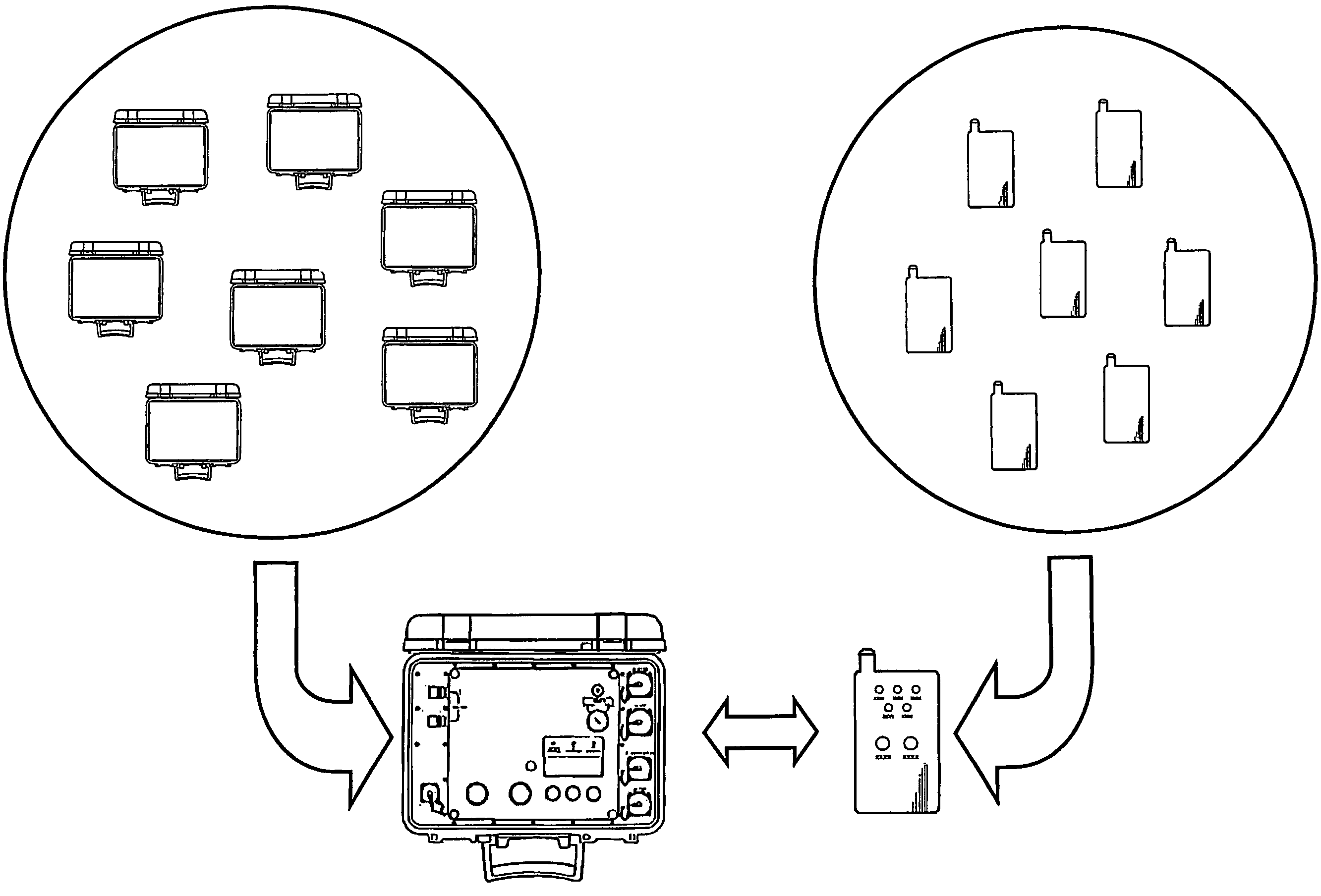
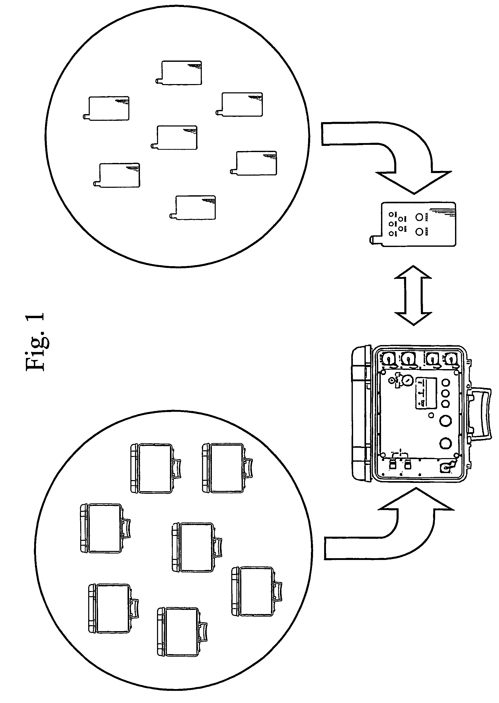
[0053]FIG. 1 illustrates the main components of a detonator system according to the invention. The system comprises a portable operating device and a control unit, such as a blasting machine. The control unit is connected to a number of detonators, which together constitute a round. The operating device is used to transmit commands or operating data to the control unit, which in turn is adapted to control the detonators in the round and cause detonation thereof.

[0054]A summary review of the system will be presented below with reference to FIG. 1.

[0055]The control unit, which usually consists of a blasting machine, and the operating device are both equipped with means for radio communication, which enables them to communicate by sending and receiving radio signals. In addition, the blasting machine and the operating device are equipped with batteries, which supply the current to each device.

[0056]The blasting machine is adapted to cause firing of the round. To this end, it is connect...


PUM


Abstract

A method for wirelessly transmitting data to a control unit, such as a blasting machine, selected from a plurality of control units from an operating device selected from a plurality of operating devices, and a system intended for the method. The control unit is connected to a plurality of detonators, which are controlled by the control unit via an electrical wire or a fuse. The operating device is associated with the appropriate control unit in a step in which address data and / or encryption data is exchanged between the units. Only one operating device can be associated with a pre-determined control unit at any given moment. The data transmitted in accordance with the method preferably comprises at least a fire command, which instructs the control unit to fire the detonators.

Description

FIELD OF THE INVENTION[0001]The present invention generally relates to a detonator system for use in blasting operations. More specifically, the present invention relates to a method and a system for wirelessly controlling a detonator system by means of a, preferably portable, operating device. The invention further relates to a control unit and an operating device for implementing the method.BACKGROUND ART[0002]A detonator is usually used to cause detonation of a large explosive charge, even though detonators themselves, in some cases, can be used as charges. In blasting operations, bores are drilled in which explosives are applied to create a charge. A detonator is arranged in or adjacent to the explosive, which is set off by the intermediary of the detonator.[0003]In large blasting operations, it is often desirable to create a carefully calculated delay of the detonation of the detonators for the purpose of obtaining a desired blasting sequence. The delay is achieved in various w...

Claims


Application Information

Patent Timeline
Patent Type & Authority Patents(United States)
IPC IPC(8): F42D1/055F42D1/04
CPCF42D1/055
Inventor BOKVIST, LEGAL REPRESENTATIVE, ANNE-MARIEJONSSON, ELOFWESTBERG, JANHALLIN, SUNE
Owner DETNET SOUTH AFRICA (PTY) LTD
Why Eureka
Try Eureka