
Air horn with light signal

a technology of air horn and light signal, which is applied in direction finders using ultrasonic/sonic/infrasonic waves, instruments, etc., can solve the problem of releasing pressurized air through the trumpet fixture to produce a loud horn nois

Inactive Publication Date: 2008-05-13
TOMASSETTI LOUIS +1
View PDF30 Cites 7 Cited by
  • Summary
  • Abstract
  • Description
  • Claims
  • Application Information

AI Technical Summary

Benefits of technology

[0008]The present invention is directed to an horn device that includes a trumpet fixture which removably attaches to the valve portion of a canister containing a charge of compressed air. An actuator button on the trumpet fixture is operable to open the valve assembly of the canister, causing release of the pressurized air through the trumpet fixture to produce a loud horn noise. The trumpet fixture is provided with one or more light signal lamps. In a preferred embodiment, the light signal lamps are powered by one or more batteries carried on the trumpet fixture. In a further embodiment, a light emitting lamp on the rear facing end of the trumpet fixture is covered with a split color lens, having a green half and a red half to provide auxiliary navigational running lights of a water vessel. In still a further embodiment, the light emitting lamp is provided in a light signaling device which is hingedly attached to the trumpet fixture. Control buttons allow selective activation of the light signal lamps in one or more modes of operation (e.g. steady, flash, flash sequence).

Problems solved by technology

An actuator button on the trumpet fixture is operable to open the valve assembly of the canister, causing release of the pressurized air through the trumpet fixture to produce a loud horn noise.

Method used


Image

  • Air horn with light signal
  • Air horn with light signal
  • Air horn with light signal

Examples


Embodiment Construction

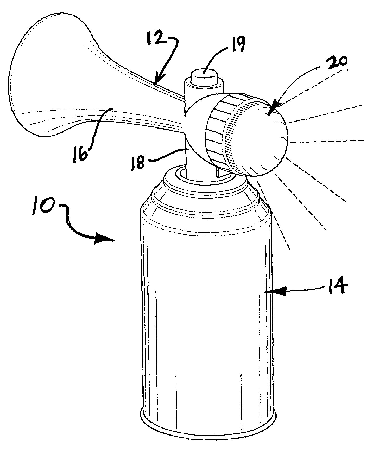
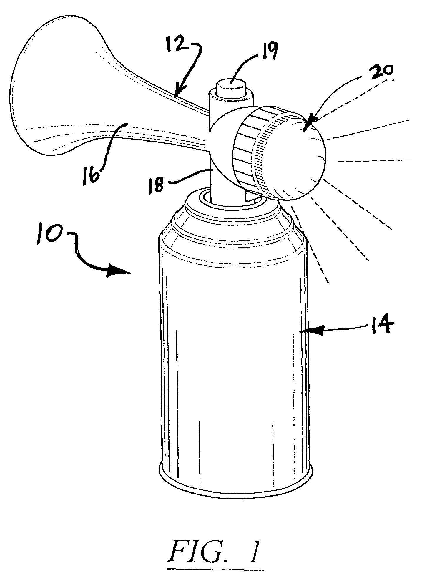
[0016]Referring to the several views of the drawings, and initially FIG. 1, the air horn device of the present invention is shown and is generally indicated as 10. The air horn includes a trumpet fixture 12 which removably attaches, by screw thread engagement, to a top nozzle fitting on canister 14. The canister 14 is filled with a charge of pressurized air. A trumpet nozzle 16 extends out from an actuator section 18 having an actuator button 19 on the top. Operation of the actuator button 19 serves to open the valve fitting on the canister 14, thereby releasing pressurized air through the actuator portion 18 and outwardly through the trumpet nozzle 16, creating a loud horn noise.

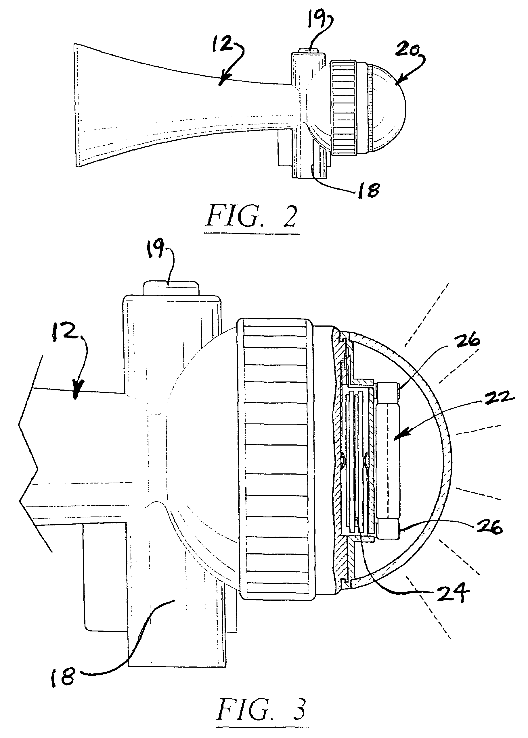
[0017]In each of the embodiments shown and described hereinafter, the horn device is provided with at least one light signal on the trumpet fixture 12. Referring initially to FIG. 1, a light signal 20 is provided on the rear facing end of the trumpet fixture 12. As seen in FIG. 3, an electric light emitting...


PUM


Abstract

A horn device includes a trumpet fixture which removably attaches to the valve portion of a canister containing a charge of compressed air. An actuator button on the trumpet fixture is operable to open the valve assembly of the canister causing release of the pressurized air through the trumpet fixture to produce a loud horn noise. One or more light signal lamps are provided on the trumpet fixture. In a preferred embodiment, the light signal lamps are powered by one or more batteries carried on the trumpet fixture. In a further embodiment, a light emitting lamp on the rear facing end of the trumpet fixture is covered with a split color lens, having a green half and a red half to provide auxiliary running lights of a water vessel. In still a further embodiment, the light emitting lamp is provided in a light signaling device which is hingedly attached to the trumpet fixture. Control buttons allow selective activation of the light signal lamps in one or more modes of operation (e.g. steady, flash, flash sequence).

Description

[0001]This application is based on provisional patent application Ser. No. 60 / 639,376 filed on Dec. 24, 2004 for which applicant claims the benefit under Title 35, United States Code section 119 (e).BACKGROUND OF THE INVENTION[0002]1. Field of the Invention[0003]The present invention is directed to portable air horn devices which operate on compressed air and, more particularly, to a hand held, self-contained air horn device which includes a trumpet fixture attached to the valve structure of a compressed air canister and one or more light emitting signaling devices on the trumpet fixture.[0004]2. Discussion of the Related Art[0005]Hand held air horn devices of the type which operate with use of compressed air released from a canister are well known in the art. Air horns of this type normally have a trumpet fixture which includes an actuator button and a cone-shaped trumpet nozzle which is configured to produce a loud horn blast when air is released from the canister and through the ...

Claims


Application Information

Patent Timeline
Patent Type & Authority Patents(United States)
IPC IPC(8): G08B7/00G10K9/04
CPCG08B3/00G08B5/36G08B7/00Y10S116/44
Inventor TOMASSETTI, LOUISTOMASSETTI, PETER
Owner TOMASSETTI LOUIS
Learn More