Take up-type screen device whose lock is releasable from either inside or outside

a screen device and lock technology, applied in the direction of door/window protective devices, shutters/movable grilles, insect protection, etc., can solve the problems of difficult positional adjustment of the locking mechanism along the structure of the window screen device is extremely simple, and the lock mechanism of the movable frame member engaged with the locking frame member cannot be unlocked. , to achieve the effect of simple structure, easy repositioning, and high locking function

Inactive Publication Date: 2008-05-13
SEIKI SOGYO
View PDF11 Cites 30 Cited by
  • Summary
  • Abstract
  • Description
  • Claims
  • Application Information

AI Technical Summary

Benefits of technology

[0006]Accordingly, it is an object of the present invention to provide a simple-structured windable screen device that can be unlocked from both the inside and the outside of a building.
[0007]Furthermore, it is another object of the present invention to provide a windable screen device including a locking element that can be unlocked from both the inside and the outside of a building, in which the locking element can be easily adjusted to any position along the movable-frame member without leaving hardly any attachment marks.
[0008]Furthermore, it is another object of the present invention to provide a windable screen device provided with a locking mechanism, in which a machining process for, for example, a screw hole for mounting the locking element is not required when the locking element is to be mounted to the movable-frame member or when the locking element is subject to repositioning on the movable-frame member. Specifically, the locking element can simply be mounted to the movable-frame member by providing a small through-hole for inserting a transmission pin at the position where the locking element is to be mounted.
[0009]Furthermore, it is another object of the present invention to provide a windable screen device, in which interior and exterior units provided in the locking element can be easily aligned via the transmission pin.
[0017]Furthermore, since such disengagement of the locking element can be performed by operating the hooking component or the operating component to rotate the hooking component in the unlocking direction against the biasing force of the spring member, the locking element achieves a high locking function while having a simple structure.
[0018]Furthermore, according to the windable screen device, the screw-hole-equipped plates are disposed in the T-shaped attachment grooves in cross-section, which extend longitudinally along the opposite side surfaces of the movable-frame member. The screws screwed in the screw holes of the screw-hole-equipped plates allow the attachment plates of the interior and exterior handle units to be secured in the attachment grooves in an adjustable manner such that the interior and exterior handle units can be adjustably positioned along the attachment grooves or can easily be repositioned. Such repositioning of the interior and exterior handle units can easily be performed by simply forming a new small through-hole for the transmission pin at the position where the interior and exterior handle units are to be disposed. This means that a machining process for, for example, a screw hole for mounting the locking element is not required, and moreover, only leaves the previous small through-hole in the attachment grooves, which was used before the repositioning of the handle units. If only a slight positional change is made, the previous small through-hole can be hidden with the locking element. Furthermore, providing such a through-hole for the transmission pin is advantageous in that the interior and exterior handle units of the locking element can be easily aligned with each other.

Problems solved by technology

However, such conventional windable screen devices have an extremely simple structure and are problematic in that the locking mechanism of the movable-frame member engaged with the locking-frame member can only be unlocked from the inside of the building.
This is problematic in cases where the person might desire to bring in objects through the opening of the building or to simply enter the building through the opening.
Moreover, because the locking mechanism is generally firmly fixed to the movable-frame member in such conventional windable devices, the positional adjustment of the locking mechanism along the movable-frame member is difficult.
Performing such an adjustment regardless of its difficulty may result in attachment marks, such as holes and openings, left on the movable-frame member that were used in the previous attachment.

Method used


Image

  • Take up-type screen device whose lock is releasable from either inside or outside
  • Take up-type screen device whose lock is releasable from either inside or outside
  • Take up-type screen device whose lock is releasable from either inside or outside

Examples


first embodiment

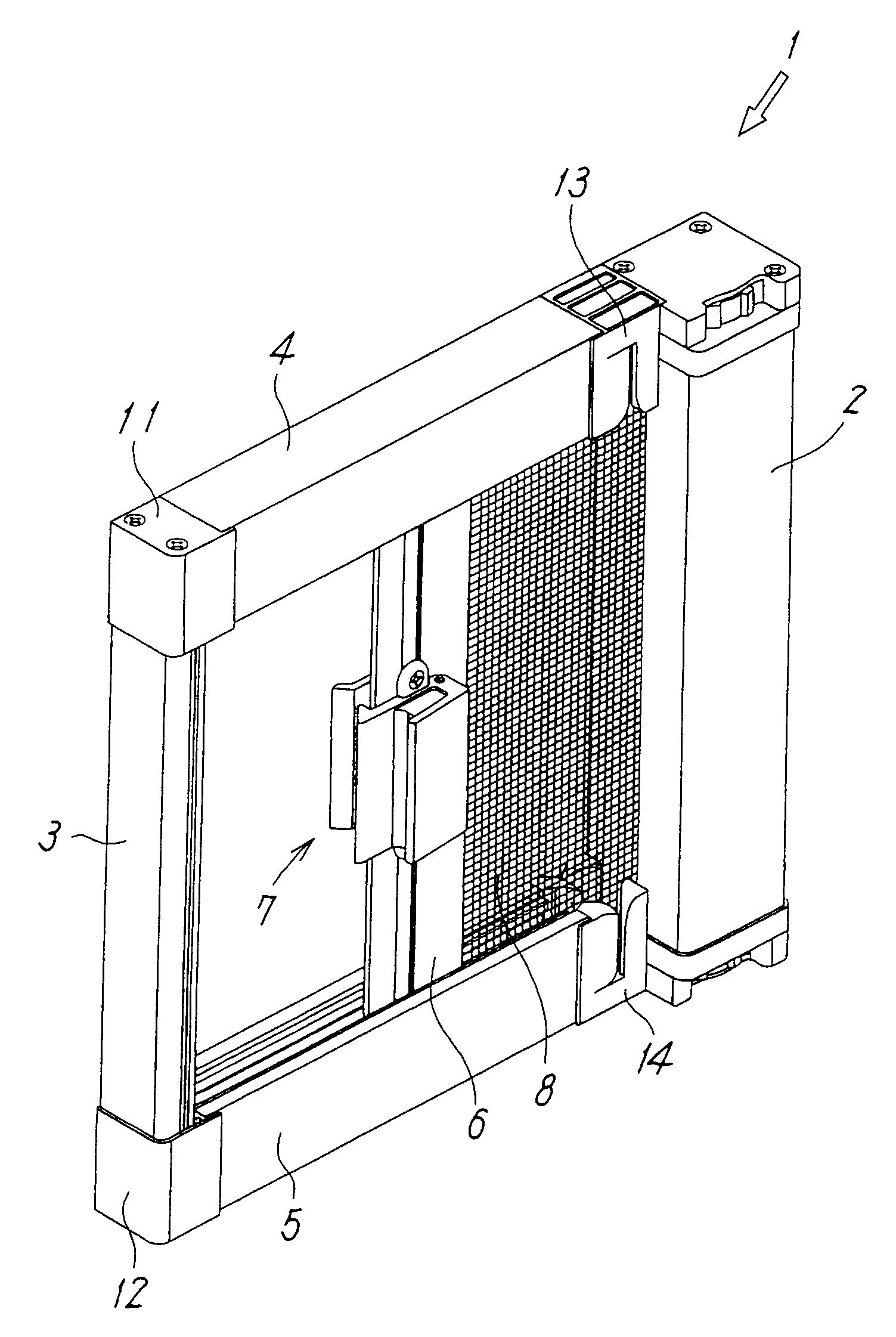
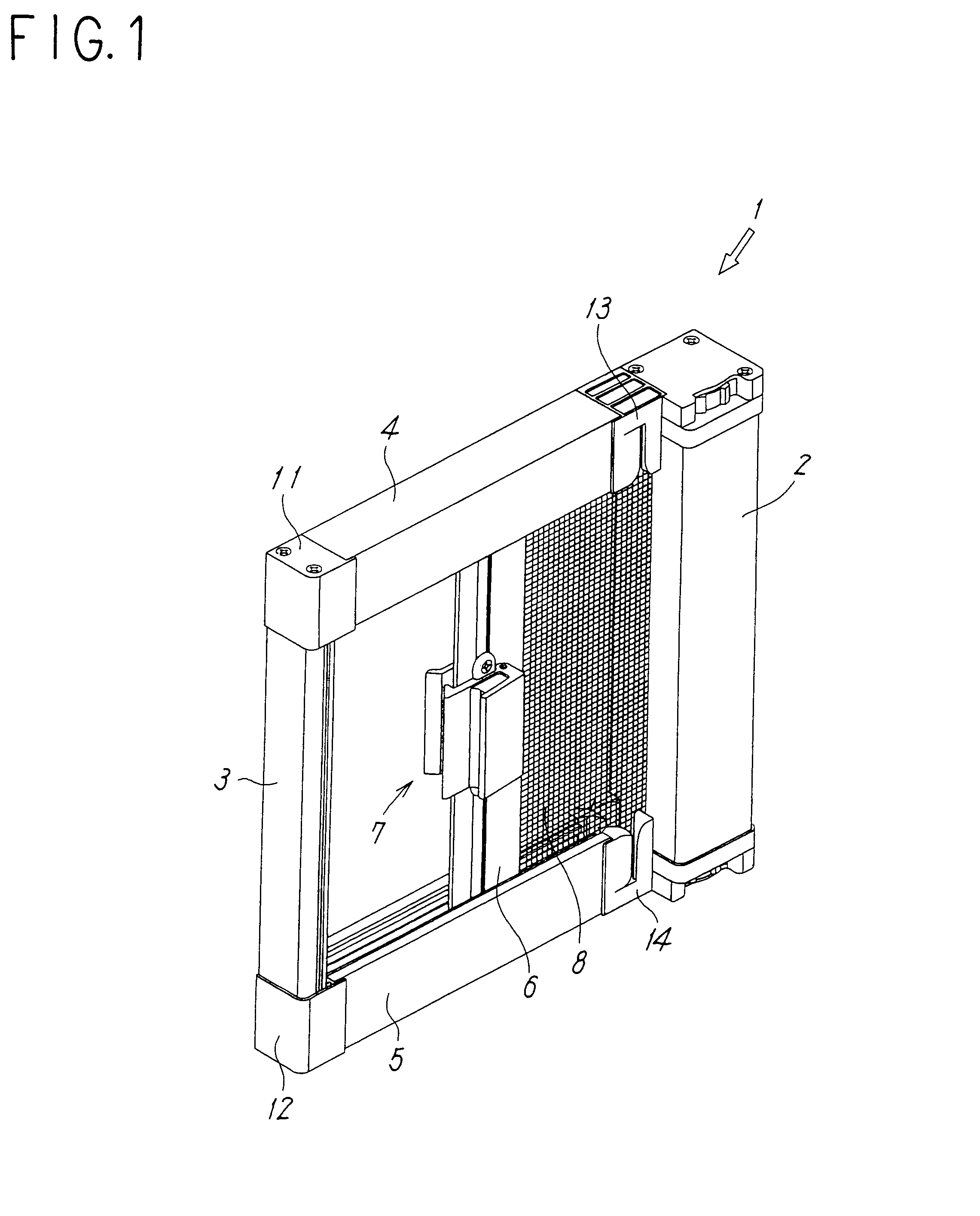
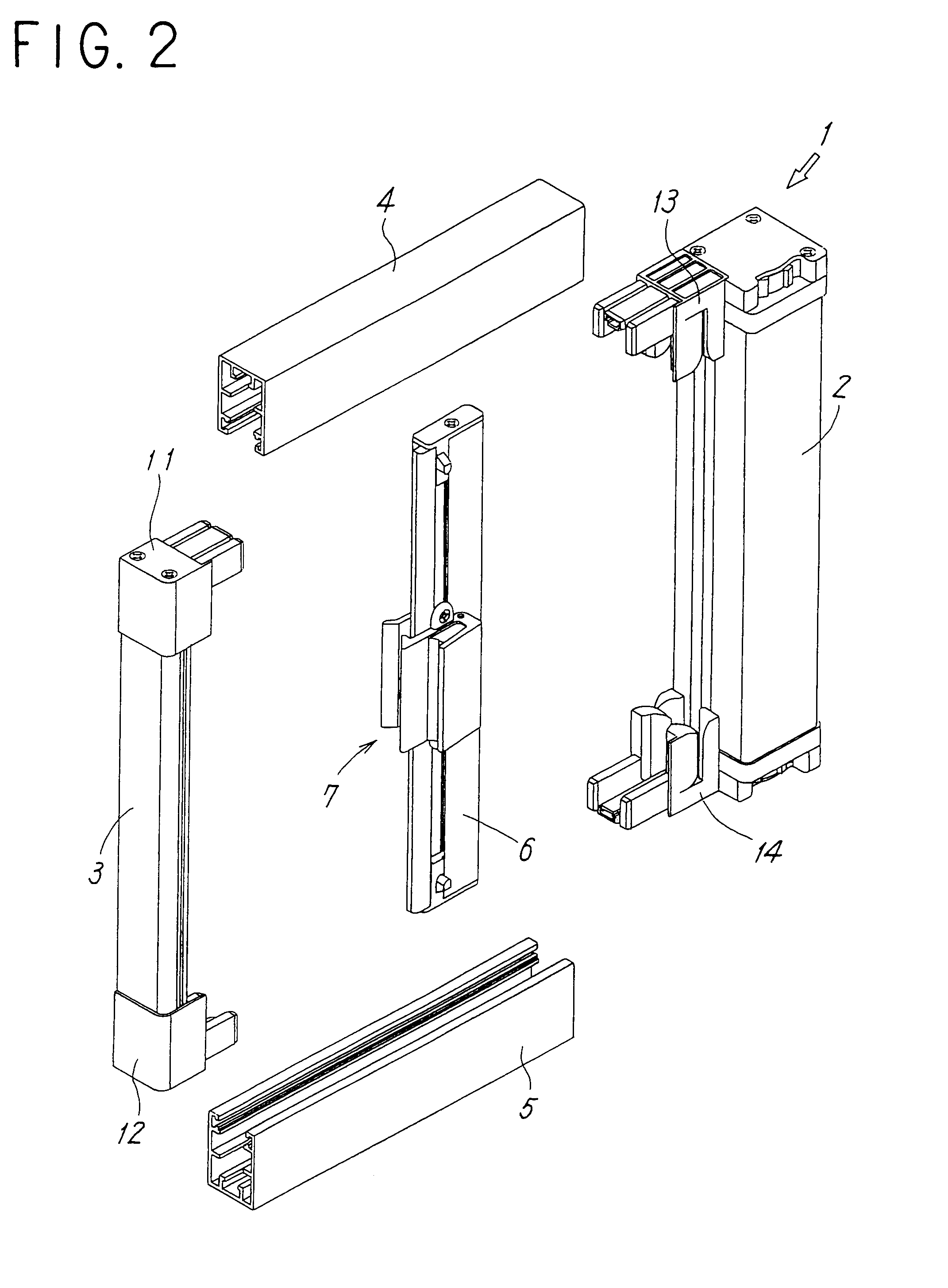
[0035]Embodiments of the present invention will now be described with reference to the drawings. FIGS. 1 to 5 illustrate a first embodiment in which a windable screen device according to the present invention is applied to a side-sliding fly-screen door.

[0036]Referring to FIGS. 1 and 2, a fly-screen door 1 includes a winding box 2 fixed to one of side-frames (not shown in the drawings) disposed along one side of an opening of a building; a stationary locking-frame member 3 fixed to the other side-frame (not shown in the drawings) disposed along the other side of the opening of the building; upper and lower guide rails 4 and 5 respectively mounted to upper and lower frames disposed along the upper and lower sides of the opening of the building; a screen 8, i.e. a fly-screen, which can be opened and closed by being moved along the upper and lower guide rails 4 and 5; a movable-frame member 6 whose one side is fixed to the screen 8 and which can be operated so as to open or close the s...

second embodiment

[0055]FIGS. 12(A) and 12(B) illustrate a second embodiment in which the locking element 7 is provided in a windable double-sliding-screen device.

[0056]Although the locking-frame member 3 is fixed to an opening of a building in the single-sliding screen device described above, the double-sliding screen device of the second embodiment is provided with a second movable-frame member 60 in place of the stationary locking-frame member 3, such that the movable-frame member 60 functions as a movable locking-frame member. In this case, the hooking component 23 of the movable-frame member 6 is engageable with an engagement portion 61 provided in the second movable-frame member 60.

[0057]Like the movable-frame member 6, the second movable-frame member 60 has a long-plate structure provided with the attachment grooves 36, 43, and 44 which are T-shaped in cross-section. Although the second movable-frame member 60 basically has the same structure as the movable-frame member 6, the second movable-f...


PUM


Abstract

The present invention provides a simple-structured windable screen device provided with a locking element that can be unlocked both from the inside and the outside of a building. According to such a windable screen device, a locking element 7 attached to a movable-frame member 6 includes interior and exterior handle units 19 and 20 respectively attached to an inner side and an outer side of the movable-frame member; a hooking component 23 which is rotatably attached to an attachment plate 21 of the interior handle unit 19 and is engageable with a locking-frame member 3; a spring member 24 which rotatably biases the hooking component 23 in a locking direction; an operating component 25 rotatably attached to an attachment plate 22 of the exterior handle unit 20; and a transmission pin 26 which extends through the movable-frame member 6 in a slidable manner such that the transmission pin 26 transmits a rotation, generated when one of the hooking component 23 and the operating component 25 is pressed, to the other one of the hooking component 23and the operating component 25.

Description

TECHNICAL FIELD[0001]The present invention relates to a windable screen device, such as a windable fly-screen door and a windable blind, which is installed in an opening of a building and can allow a screen to be opened and closed by rotating a winding shaft.BACKGROUND ART[0002]In conventional windable screen devices installed in an opening of a building for insect prevention, light-shielding, or insulation, one end of a screen, such as a fly-screen, is fixed to a movable-frame member, which can be operated to open or close the screen, and the other end of the screen is fixed to a winding shaft provided with a spring which functions as a driving source for winding the screen. Thus, the winding shaft rotates in forward and reverse directions so as to wind and unwind the screen.[0003]In such conventional screen devices, the winding shaft is generally housed in a winding box fixed to one of side-frames disposed along one side of an opening of a building, and a locking-frame member is f...

Claims


Application Information

Patent Timeline
Patent Type & Authority Patents(United States)
IPC IPC(8): E06B9/56E06B9/54E06B9/80E06B9/86
CPCE06B9/54E06B2009/543
Inventor MORIYA, HIROFUMIMORIYA, TAKASHI
Owner SEIKI SOGYO
Why Eureka
Try Eureka