Check patentability & draft patents in minutes with Patsnap Eureka AI!

Label switched path OAM wrapper

a switched path and label technology, applied in the field of communication networks, can solve the problems of inability to consider the performance of the network segment between these ingress and exit points, the failure detection/management method of the mpls network, and the inability to detect/manage the fault of the network segment,

Inactive Publication Date: 2008-05-13
RPX CLEARINGHOUSE
View PDF27 Cites 105 Cited by
  • Summary
  • Abstract
  • Description
  • Claims
  • Application Information

AI Technical Summary

Benefits of technology

[0009]The present invention seeks to provide methods for logically segmenting an LSP so that OAM DTUs may be used to determine the performance and / or the status of LSP segments. To segment a previously determined LSP, a dedicated subpath (a logical LSP) within that predetermined LSP is defined between two LSRs that are capable of processing OAM DTUs. The source node (source LSR) establishes a logical LSP between itself and the destination node (destination LSR) using an LDP. In doing this, the logical LSP traverses a specific path and transits through specific nodes in that path. The destination node then transmits an OAM DTU or any other specialized DTU to the source node using a label specifically associated with the logical LSP that was established. The characteristic of the specific path traversed by the logical LSP can thus be determined by when, how, and if the specialized DTU is received by the destination node.

Problems solved by technology

While the MPLS standard promises great benefits, very few methods have been developed for fault detection / management of an MPLS network.
This approach, unfortunately, only allows for performance determination between these ingress and egress points.
The performance of network segments between these ingress and egress points is not possible nor even considered in the above proposal.
Furthermore, the use of a specific MPLS label value for OAM packets leads to increased overhead costs for this proposal.

Method used


Image

  • Label switched path OAM wrapper
  • Label switched path OAM wrapper
  • Label switched path OAM wrapper

Examples


Embodiment Construction

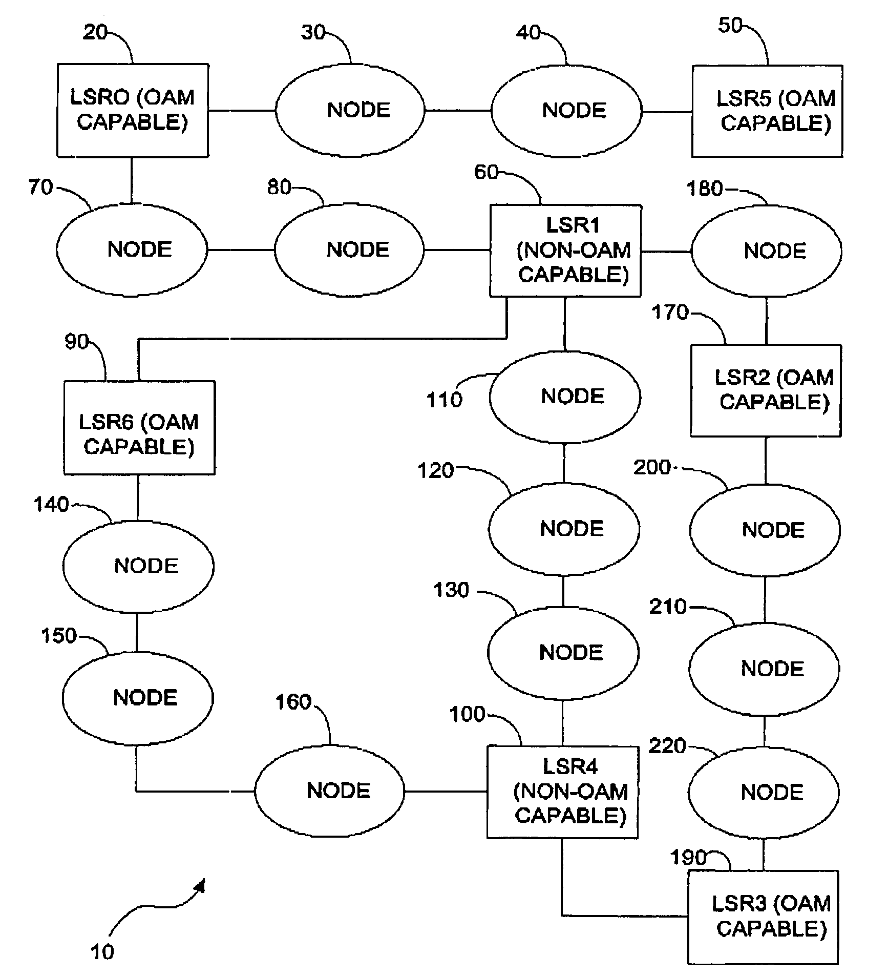
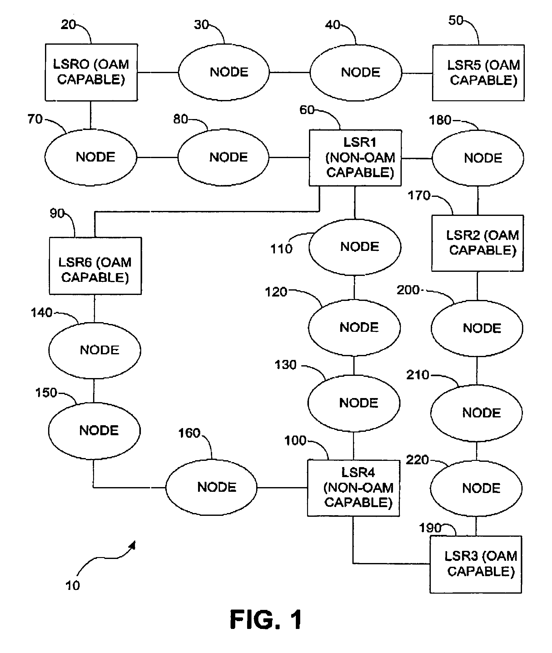
[0043]For this document, the term “OAM-capable” will be understood to mean capable of processing OAM DTUs or some other specialized DTU used for maintenance and / or performance determination purposes. Processing such DTUs may involve producing such DTUs, determining network segment performance from the DTUs and determining network or network segment faults by the receipt or non-receipt of such DTUs. Based on the above, a “non-OAM capable” node will thus be nodes that are unable to process such specialized DTUs.

[0044]Referring to FIG. 1, a schematic block diagram of an MPLS network 10 is illustrated. A first OAM capable LSR 20 (LSR0) is coupled to a node 30. The node 30 is coupled to another node 40 which, in turn, is coupled to a second OAM capable LSR 50 (LSR5). At another end of LSR 20, a non OAM capable LSR 60 (LSR1) is coupled to LSR 20 through two intervening nodes 70, 80. This non-OAM capable LSR 60 is also coupled to another OAM capable LSR 90 (LSR6) with no intervening nodes ...


PUM


Abstract

Methods and devices for logically segmenting an LSP so that OAM DTUs may be used to determine the performance and / or the status of LSP segments. To segment a previously determined LSP, a dedicated subpath (a logical LSP) within that predetermined LSP is defined between two LSRs that are capable of processing OAM DTUs. The source node (source LSR) establishes a logical LSP between itself and the destination node (destination LSR) using an LDP. In doing this, the logical LSP traverses a specific path and transits through specific nodes in that path. The source node then transmits an OAM DTU or any other specialized DTU to the destination node using a label specifically associated with the logical LSP that was established. The characteristic of the specific path traversed by the logical LSP can thus be determined by when, how, and if the specialized DTU is received by the destination node.

Description

FIELD OF THE INVENTION[0001]The invention relates to communications networks and, more particularly, to methods and devices for determining the performance of network segments in a Multi-Protocol Label Switched (MPLS) network.BACKGROUND OF THE INVENTION[0002]Today's increasing use of and reliance on communications networks has led to the development of new standards and protocol that provide more reliable and efficient network services to consumers.[0003]A standard that is still developing is MPLS (Multi-Protocol Label Switching). This emerging standard allows packets or any data transmission units (DTUs) to be routed in the MPLS network based simply on a label that the DTU is carrying. This process facilitates the complexity of route lookups that are based on a destination IP (Internet Protocol) address. Thus, a DTU (Data Transmission Unit) arriving at a router is forwarded to another router based merely on the a DTU's label. At the next router, the label of the DTU may be replaced...

Claims


Application Information

Patent Timeline
Patent Type & Authority Patents(United States)
IPC IPC(8): G06F15/173G06F11/00G06F15/16H04L45/50
CPCH04L41/04H04L45/50H04L41/12H04L41/34
Inventor AZAD, MINA M.
Owner RPX CLEARINGHOUSE
Features
  • R&D
  • Intellectual Property
  • Life Sciences
  • Materials
  • Tech Scout
  • Unparalleled Data Quality
  • Higher Quality Content
  • 60% Fewer Hallucinations
Learn More