
High temperature pressure transmitter assembly

a transmitter and high temperature technology, applied in the direction of fluid pressure measurement by mechanical elements, fluid pressure measurement using elastically deformable gauges, instruments, etc., can solve the errors of pressure measurement, increase the cost and complexity of installation, and reduce the accuracy of pressure measuremen

Active Publication Date: 2008-05-20
ROSEMOUNT INC
View PDF31 Cites 18 Cited by
  • Summary
  • Abstract
  • Description
  • Claims
  • Application Information

AI Technical Summary

Benefits of technology

[0006]Typically, a pressure transmitter includes a pressure sensor which couples to the pressure of the process fluid through an isolation system. The isolating system can comprise, for example, a isolation diaphragm which is in physical contact with the process fluid and an isolation fill fluid which extends between the isolation diaphragm and the pressure sensor. The fill fluid preferably comprises a substantially incompressible fluid such as oil. As the process fluid exerts a pressure on the isolation diaphragm, changes in the applied pressure are conveyed across the diaphragm, through the isolation fluid and to the pressure sensor. Such isolation systems prevent the delicate components of the pressure sensor from being directly exposed to the process fluid.
[0008]The introduction of the remote seal configuration increases the cost and complexity of the installation and reduces the accuracy of the pressure measurements. Further, the additional components provide another source of possible failure of the device.SUMMARY

Problems solved by technology

However, typically transmitters have a maximum operating temperature of 250-300° F. Even in cases where the transmitter can withstand the high temperature, temperature extremes can still cause errors in pressure measurements.
The introduction of the remote seal configuration increases the cost and complexity of the installation and reduces the accuracy of the pressure measurements.
Further, the additional components provide another source of possible failure of the device.

Method used


Image

  • High temperature pressure transmitter assembly
  • High temperature pressure transmitter assembly
  • High temperature pressure transmitter assembly

Examples


Embodiment Construction

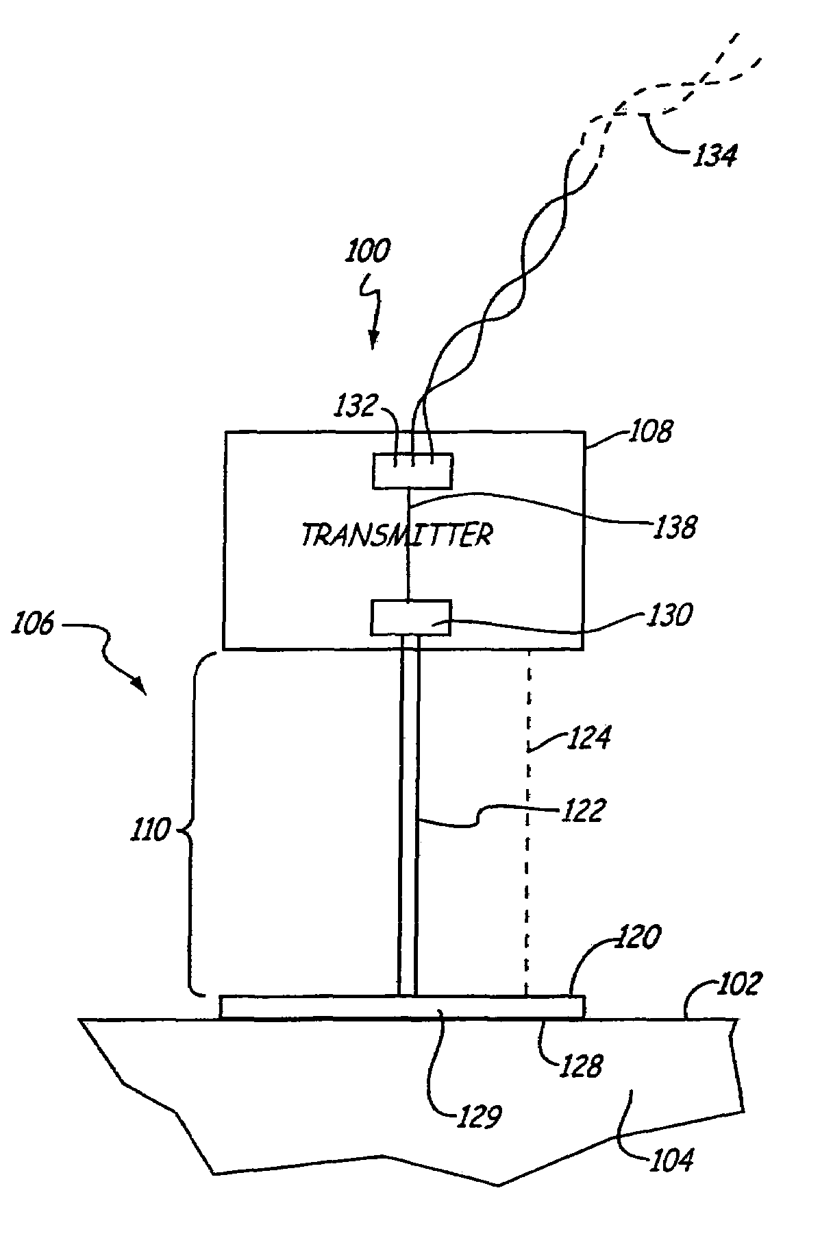
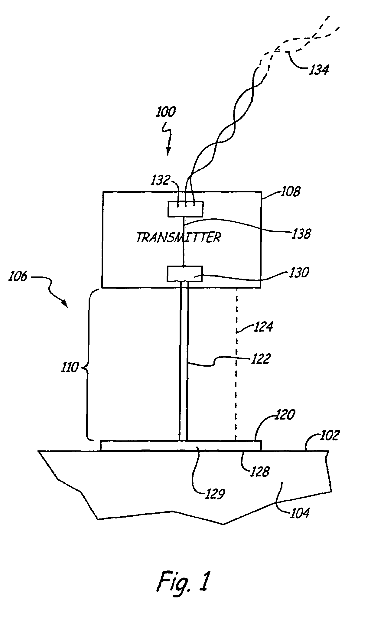
[0018]The present invention is directed to industrial transmitters of type used to measure a process variable of a process fluid in which the process fluid and / or process environment are at a relatively high temperature. With the present invention, the pressure sensor and transmitter electronics are spaced apart from the process fluid to provide thermal isolation from the process fluid. However, the configuration of the present invention does not require the remote seal technique discussed in the background section. Temperature compensation can also be employed.

[0019]Electronic industrial pressure transmitters which are employed in the process industry such as pharmaceutical, biotechnology, food and beverage technologies and others, often have special requirements. For example, they may often be required to measure the pressure of process fluid at very high temperatures. They are often required to survive very high temperatures during cleaning processes which occur between both “bat...


PUM

PropertyMeasurementUnit
current levelaaaaaaaaaa
currentaaaaaaaaaa

Abstract

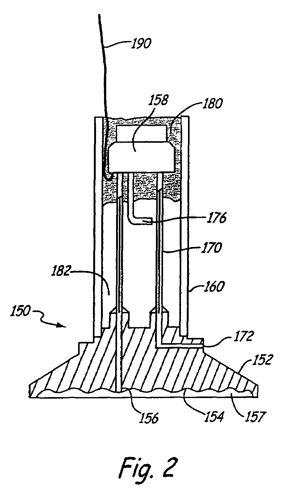
A pressure transmitter assembly for measuring a pressure of a process fluid includes an isolation diaphragm assembly configured to couple to a process fluid. A pressure sensor is coupled to the isolation diaphragm assembly and is configured to sense a pressure. An isolation diaphragm coupling flange is provided to carry the isolation diaphragm assembly and includes a cutaway portion to provide thermal isolation.

Description

BACKGROUND OF THE INVENTION[0001]The present application is a Continuation-in-Part of and claims priority of U.S. patent application Ser. No. 10 / 876,816, filed Jun. 25, 2004, the content of which is hereby incorporated by reference in its entirety.[0002]The present invention relates to process control transmitters of the type used in industrial process monitoring and control systems. More specifically, the present invention relates to transmitters which measure process variables in high temperature environments.[0003]Process monitoring and control systems are used to monitor and control operation of industrial processes. Industrial processes are used in manufacturing to produce various products such as refined oil, pharmaceuticals, paper, foods, etc. In large scale implementations, these processes must be monitored and controlled in order to operate within the desired parameters.[0004]“Transmitter” has become a term which is used to describe the devices which couple to the process e...

Claims


Application Information

Patent Timeline
Patent Type & Authority Patents(United States)
IPC IPC(8): G01L7/08G01L19/00G01L19/04G01L19/06
CPCG01L9/025G01L19/0681G01L19/0645
Inventor BRODEN, DAVID A.
Owner ROSEMOUNT INC
Learn More