
Real-Time Stereo 3D Digital/Video Imaging in a Light Microscope Using a Single Lens and a Single Camera

a technology of 3d digital/video imaging and light microscope, applied in the field of microscopes, can solve the problems and the need for precise moving parts to register and align the left and right cameras, so as to achieve the effect of increasing the cost and complexity of the system

Inactive Publication Date: 2013-07-18
GREENBERG GARY
View PDF29 Cites 2 Cited by
  • Summary
  • Abstract
  • Description
  • Claims
  • Application Information

AI Technical Summary

Benefits of technology

This patent describes a way to create 3D images using a single camera and a pyramid mirror. The invention is able to perfectly align the left and right images, even at the highest resolution, without the need for expensive and complicated multi-lens systems. This technology reduces complexity and cost while still providing high-quality 3D viewing.

Problems solved by technology

While the prior art teaches how to provide direct-view 3D imaging using a single lens with two cameras by employing a pyramid mirror to dissect out the left and right images at the conjugate aperture plane located at the pupil of the eyepiece (Greenberg G, U.S. Pat. No. 6,020,993), using two cameras increases the cost and complexity of the system and requires precise moving parts to register and align the left and right cameras.

Method used


Image

  • Real-Time Stereo 3D Digital/Video Imaging in a Light Microscope Using a Single Lens and a Single Camera
  • Real-Time Stereo 3D Digital/Video Imaging in a Light Microscope Using a Single Lens and a Single Camera
  • Real-Time Stereo 3D Digital/Video Imaging in a Light Microscope Using a Single Lens and a Single Camera

Examples


Embodiment Construction

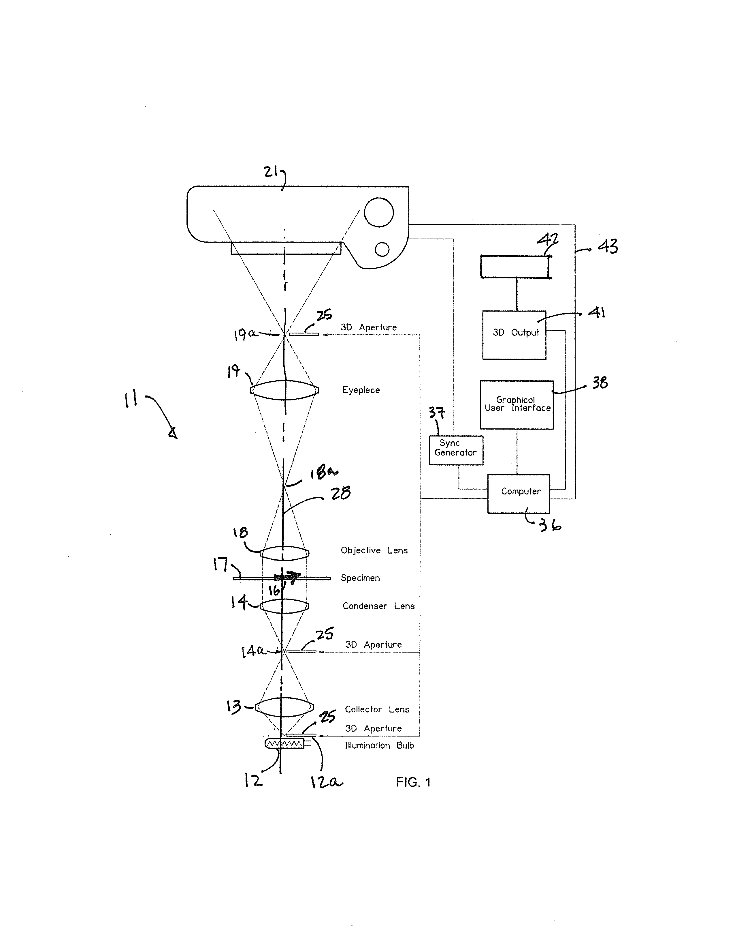
[0014]FIGS. 1 and 3 illustrate the invention in a fixed tube length microscope optical system; however, those skilled in the art will recognize that an infinity tube length system would work in a similar way, but with the addition of an infinity tube lens positioned after the infinity objective lens.

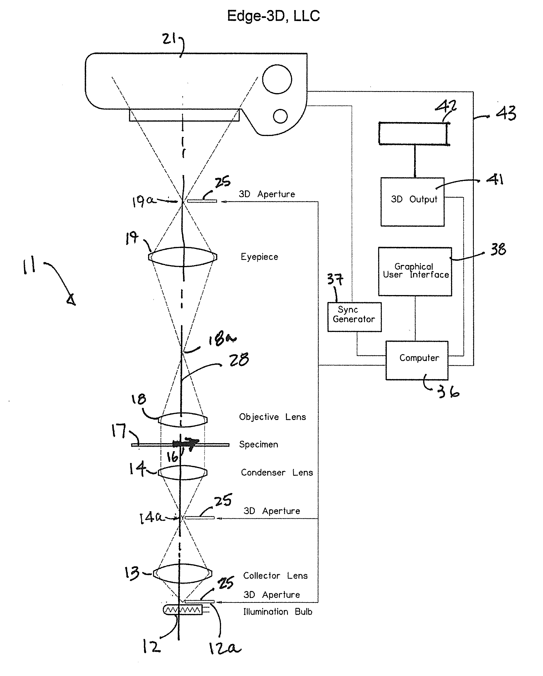
[0015]Referring to FIG. 1, a microscope optical system 11 comprises an illuminator 12 which, for purposes of illustration, is shown as a light transmitting bulb with the understanding that other light transmitting devices are also included, a collector lens 13, a condenser lens 14, a specimen 16 at a specimen plane 17, an objective lens 18, an eye piece 19, and a viewing device such as a camera 21 all aligned along an optical path 28.

[0016]There are three potentially accessible locations along the optical path 28 where a mechanical aperture mask 25 could be located including: (1) the pupil 19a of the eyepiece 19, which has the advantage of being compatible with any method of illumination...


PUM


Abstract

The methods and apparatus of the present invention provide 3D real-time viewing in a light microscope by passing light through only a portion of the objective aperture, in such a way as to produce alternating left-eye and right-eye views of the specimen. A computer with a sync pulse generator synchronizes the frame rate of the camera with the alternating left-eye and right-eye images, which are sequentially captured by the camera and reformatted into the standard side-by-side stereo file format and displayed on a 3D TV or the like, where they can be viewed in 3D in real-time.

Description

FIELD OF THE INVENTION[0001]The present invention relates to microscopes and, more particularly, to methods and apparatus for producing automated 3D images in a light microscope using a computer, shaped light beams, a single camera, and a single objective lens.BACKGROUND OF THE INVENTION[0002]Microscope specimens are three-dimensional objects, but standard light microscopes produce only two-dimensional images. Information is lost and misinterpretation occurs when viewing two-dimensional images of three-dimensional objects.SUMMARY OF THE INVENTION[0003]It is known that in a standard 2D microscope optical system, the pupil of the eyepiece, the back focal plane of the condenser lens and the illumination bulb are optically conjugate to the back focal plane of the objective lens (Koehler illumination in a transmitted light microscope).[0004]The methods and apparatus of the present invention function by sequentially creating alternating left-eye and right-eye views of a specimen at a rate...

Claims


Application Information

Patent Timeline
Patent Type & Authority Applications(United States)
IPC IPC(8): H04N13/02
CPCG02B21/22G02B21/365H04N13/0207H04N13/021H04N13/211H04N13/207
Inventor GREENBERG, GARY
Owner GREENBERG GARY
Learn More