Filter and system for improved sealing and ease of attachment on a vacuum cleaner

a vacuum cleaner and filter body technology, applied in the field of vacuum cleaner filters, can solve the problems of wear on the internal vacuum motor, the impeller, the vacuum cleaner is notoriously dusty and dirty, and the operator has difficulty in determining the compressive force to use on the filter body,

Active Publication Date: 2008-05-20
EMERSON ELECTRIC CO
View PDF12 Cites 22 Cited by
  • Summary
  • Abstract
  • Description
  • Claims
  • Application Information

AI Technical Summary

Problems solved by technology

Vacuum cleaners are notoriously dusty and dirty, requiring some method to separate the dust and the dirt from the exhaust air.
Experience has shown that operators have difficulty determining how much compressive force to use on the filter body, because such installation includes compressing the filter element as well.
At times, operators use too little force and allow leakage of fine dust, resulting in wear on the internal vacuum motor, impeller, and other internal structures.
At other times, operators apply too much force and crush the filter or strip the attachment threads, causing repair or replacement.

Method used


Image

  • Filter and system for improved sealing and ease of attachment on a vacuum cleaner
  • Filter and system for improved sealing and ease of attachment on a vacuum cleaner
  • Filter and system for improved sealing and ease of attachment on a vacuum cleaner

Examples


Embodiment Construction

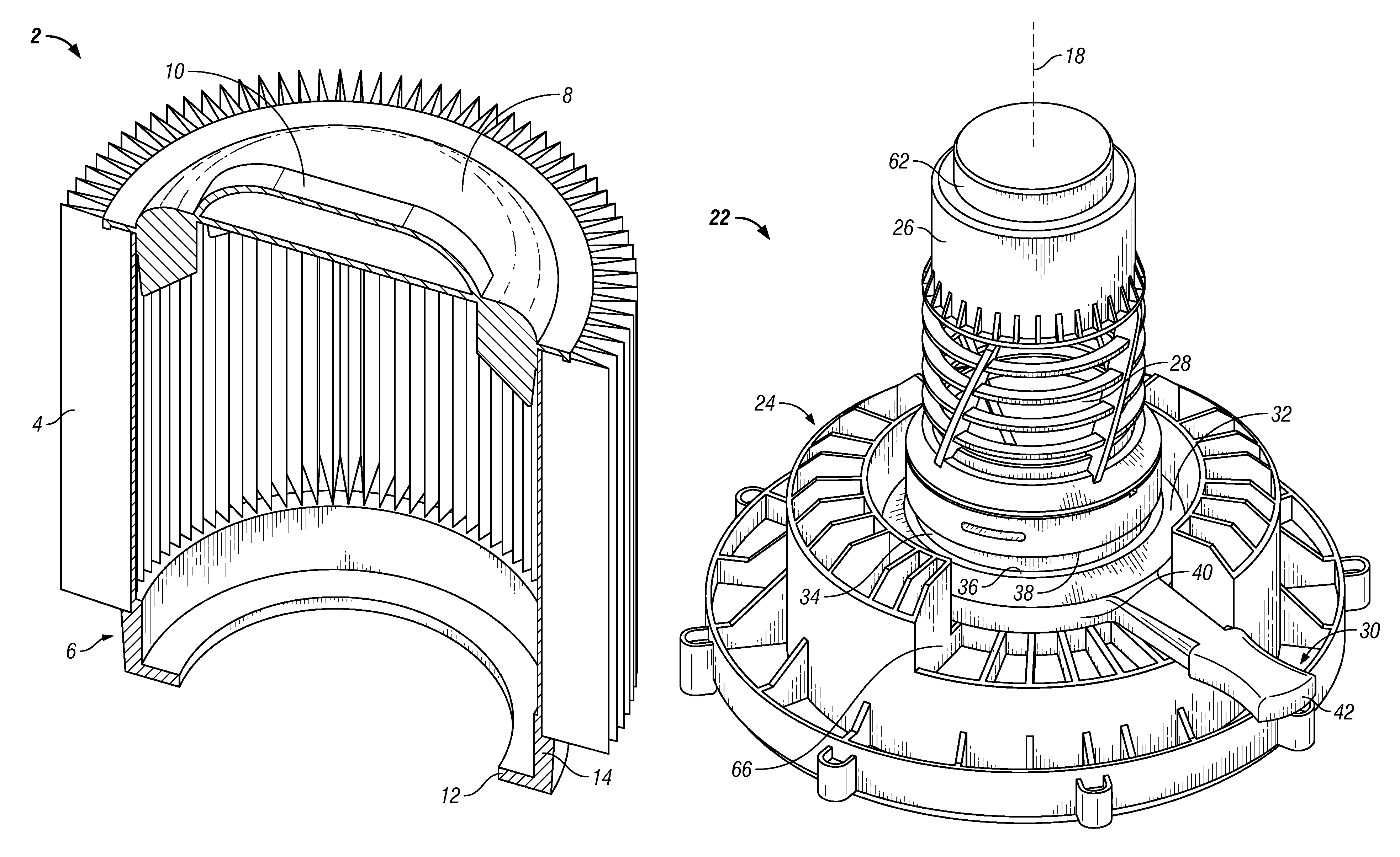
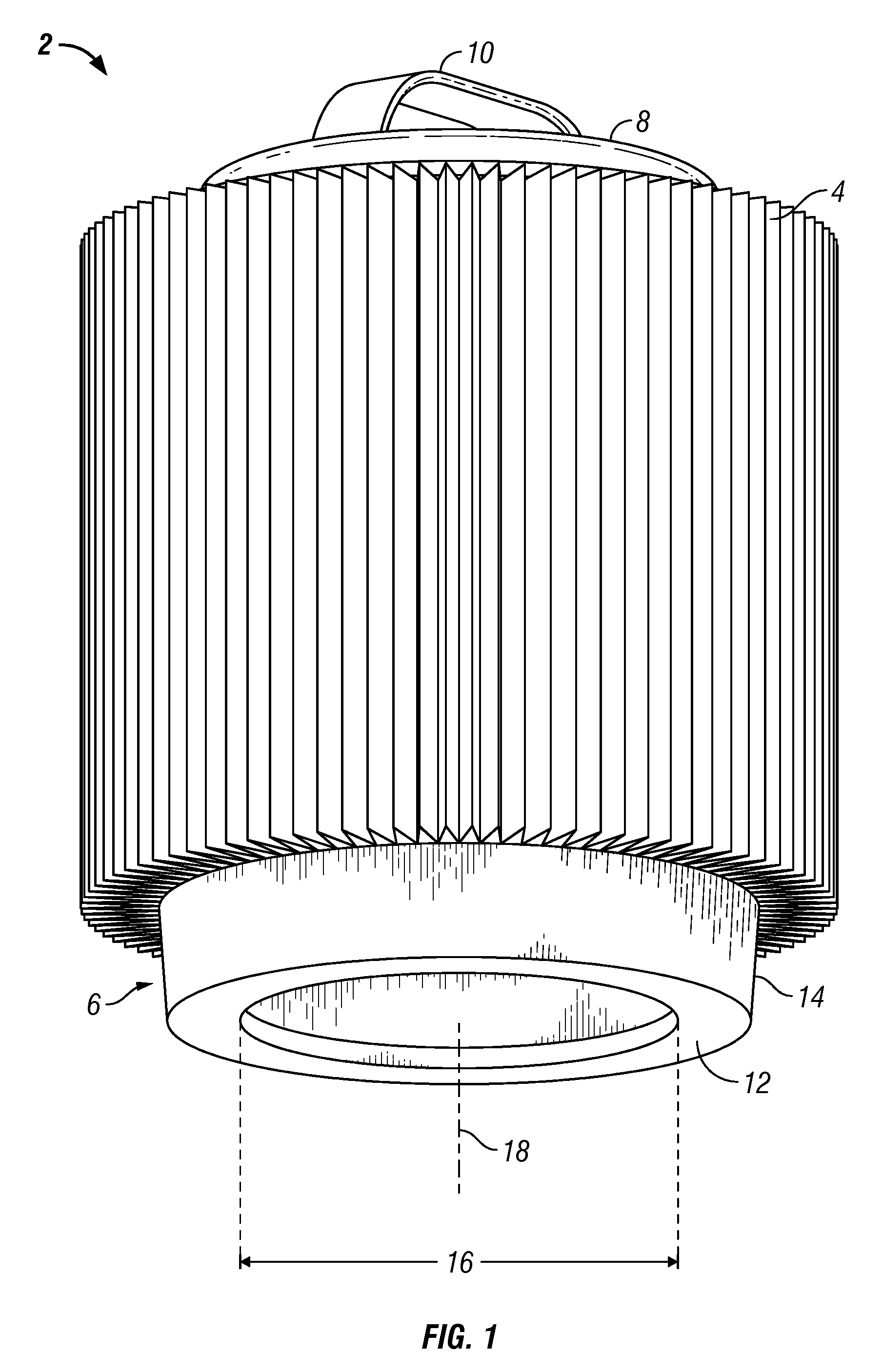
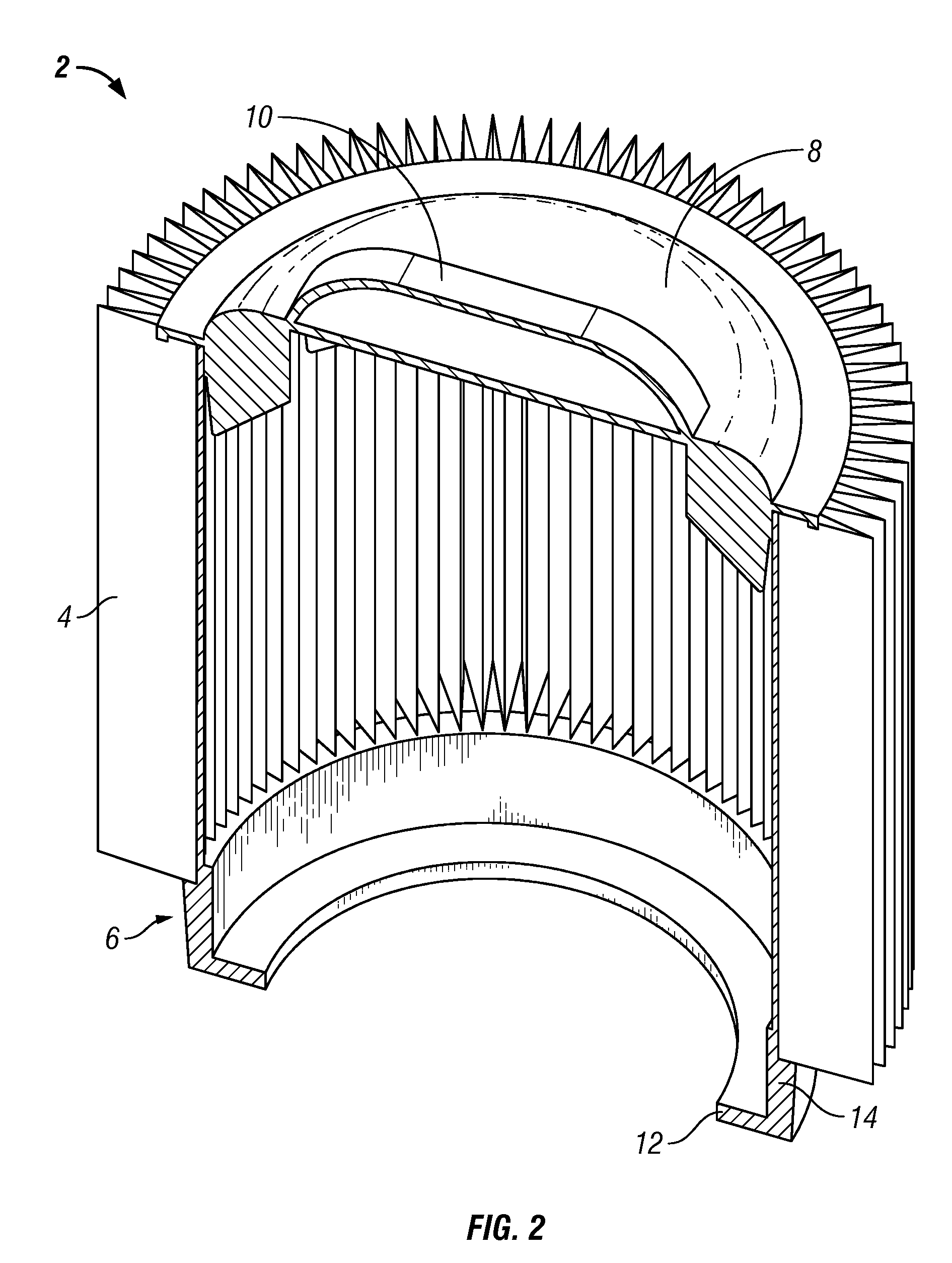
[0026]FIG. 1 is a perspective schematic view of an exemplary filter of the present disclosure. FIG. 2 is a perspective cross sectional schematic view of the exemplary filter, showing the filter seals, filter element, and cap. The figures will be described in conjunction with each other. The filter 2 includes a filter element 4 having a seal 6 disposed on a lower end (relative to the figure orientation) and a filter cap 8 disposed on an upper end distal from the seal 6. The cap 8 can include a handle 10 for convenience in handling the filter. The components are disposed along a longitudinal axis 18. The filter element is generally porous material, such as cloth or paper, and can be reinforced with metal or plastic mesh. The filter seal 6 is generally formed from a non-porous material to reduce leakage therethrough and is sealed at the interface of the filter element. Advantageously, the seal can be made of a variety of flexible elastomeric materials that can be stretched and compress...


PUM

PropertyMeasurementUnit
compressaaaaaaaaaa
elevationaaaaaaaaaa
rotationaaaaaaaaaa

Abstract

The disclosure provides a system for mounting and sealing a filter in a vacuum cleaner, such as a wet and dry vacuum cleaner, that concentrates compressive sealing forces on a specific, relatively thin seal portion rather than the filter body as a whole. The concentrated compressive stress provides a well-defined region to consistently provide a sealing engagement. A portion of the seal is positioned into an undercut portion of a mounting assembly and is compressed or “pinched” between opposing surfaces to cause the sealing. Further, one or more of the surfaces are movable to compress the seal portion therebetween by actuation of a rotatable filter clamp engageable with a cam. The filter clamp translates toward the seal portion as the filter clamp is rotated along a sloped surface of the cam to engage and clamp the seal portion between the surfaces.

Description

CROSS REFERENCE TO RELATED APPLICATIONS[0001]This application claims the benefit of U.S. Provisional Appl. No. 60 / 739,651, filed Nov. 23, 2005, the contents of which are hereby incorporated by reference.STATEMENT REGARDING FEDERALLY SPONSORED RESEARCH OR DEVELOPMENT[0002]Not applicable.REFERENCE TO APPENDIX[0003]Not applicable.BACKGROUND OF THE INVENTION[0004]1. Field of the Invention[0005]The disclosure relates to the field of vacuum cleaners. More specifically, the disclosure relates to filters for vacuum cleaners.[0006]2. Description of the Related Art[0007]Vacuum cleaners are notoriously dusty and dirty, requiring some method to separate the dust and the dirt from the exhaust air. Hence, filters are commonly used to perform this separation function. There often is a need to remove and re-attach the filter, for example, when cleaning the filter or replacing it with a new filter. With the type of vacuum cleaners known as “wet / dry” vacuum cleaners, the filter is often also removed ...

Claims


Application Information

Patent Timeline
Patent Type & Authority Patents(United States)
IPC IPC(8): B01D45/00
CPCA47L9/127B01D46/2411B01D46/4227B01D46/521B01D2265/025B01D2271/02B01D2279/55
Inventor GIERER, JOSEPH T.
Owner EMERSON ELECTRIC CO
Why Eureka
Try Eureka