
Electronic pedometer

a pedometer and electronic technology, applied in the field of pedometers, can solve problems such as false step numbers

Inactive Publication Date: 2008-05-20
SEIKO INSTR INC
View PDF9 Cites 14 Cited by
  • Summary
  • Abstract
  • Description
  • Claims
  • Application Information

AI Technical Summary

Benefits of technology

The invention is an electronic pedometer that can detect a user's motion and step count. It includes an acceleration sensor and a slant sensor to determine the user's walking direction. The slant sensor can detect if the user's pedometer is slanted in a certain direction. The electronic pedometer uses a signal processing part to determine the step number based on the acceleration sensor and slant sensor. The signal processing part can also evaluate the step number based on the horizontality sensor and compare it with the step number just before or after the evaluation. This allows for accurate step count and evaluation of the user's walking direction.

Problems solved by technology

However, not limited to the above conventional electronic pedometer, the electronic pedometer having the acceleration sensor as the walk sensor has a problem that a false step number is counted in a case where the user has moved only the arm without walking.
In other words, in the electronic pedometer having possessed the acceleration sensor, there is a problem that, if the electronic pedometer outputs the acceleration signal also by a motion of the user other than the walk, the step number is counted, so that the step number larger than a real step number is recorded and displayed.

Method used


Image

  • Electronic pedometer
  • Electronic pedometer
  • Electronic pedometer

Examples


embodiment 1

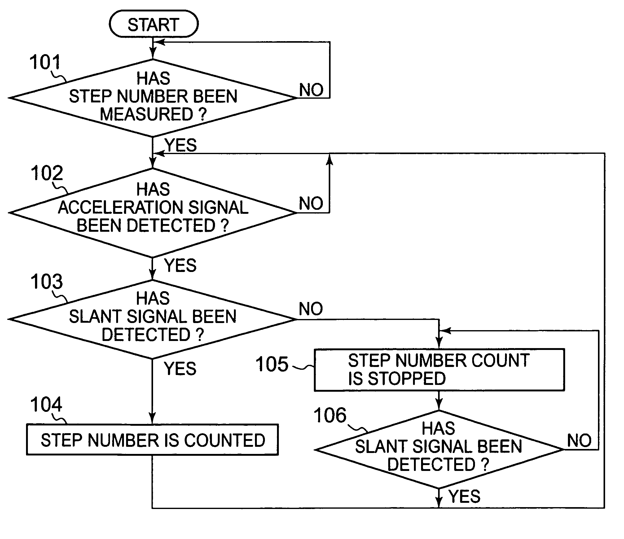
[0026]The electronic pedometer of the invention, which has been constituted as mentioned above, operates in compliance with such a processing flow as shown in FIG. 5.

[0027]The control section 11 first judges whether or not the electronic pedometer is the step number measurement mode (101). In the step 101, if it is judged to be the step number measurement mode, the control section 11 detects an existence / nonexistence of an input of an acceleration signal from the acceleration sensor 17 (102). If the input of the acceleration signal is detected in the step 102, the control section 11 judges whether or not the electronic pedometer is in a slant state on the basis of an output signal of the slant sensor 18 (103). In a case where the slant sensor 18 is outputting a slant signal, the control section 11 performs a step number count with the acceleration signal being made a step number signal (104), and it returns to the initial step 102.

[0028]In the step 103, in a case where the slant sen...

embodiment 2

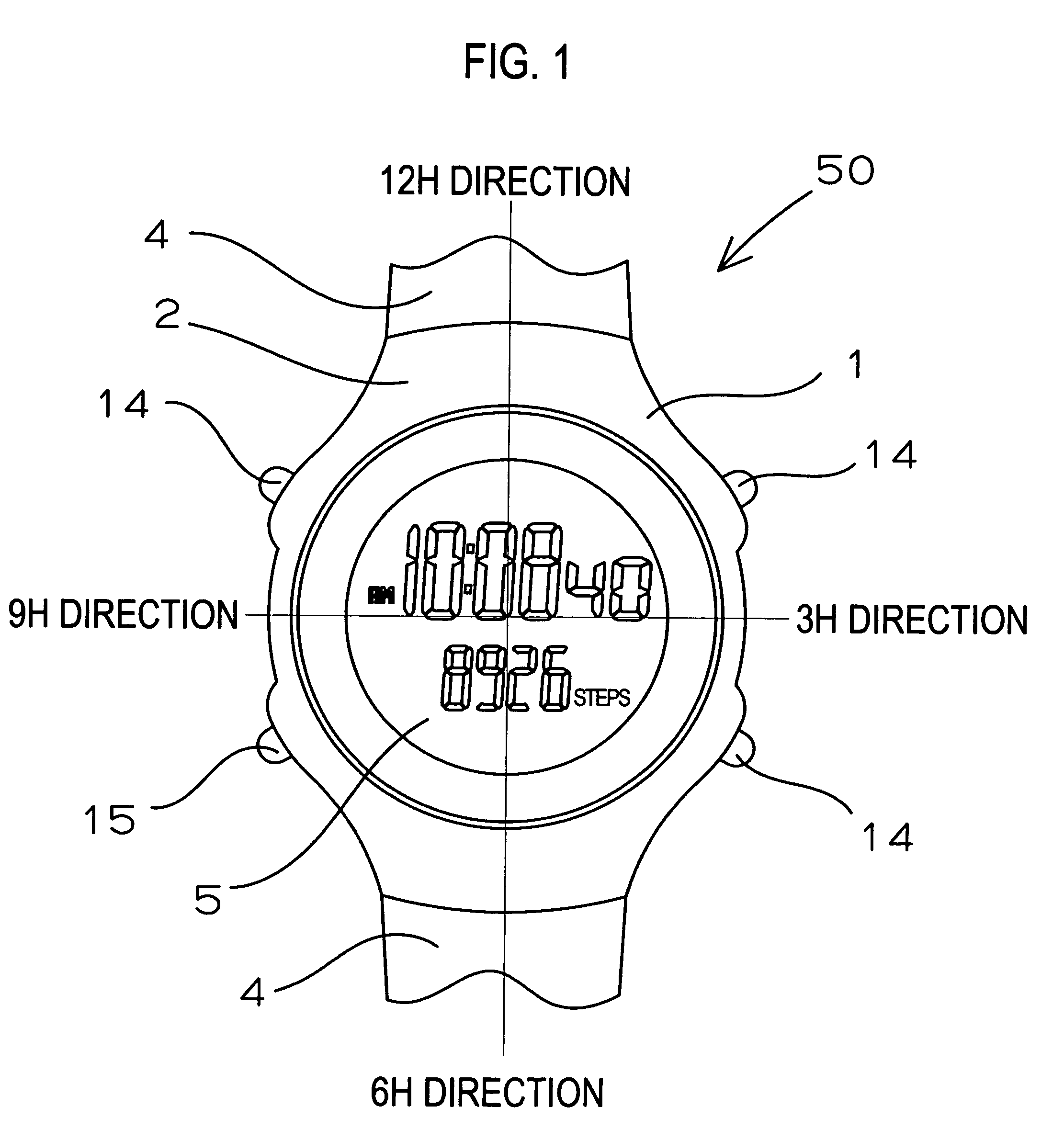
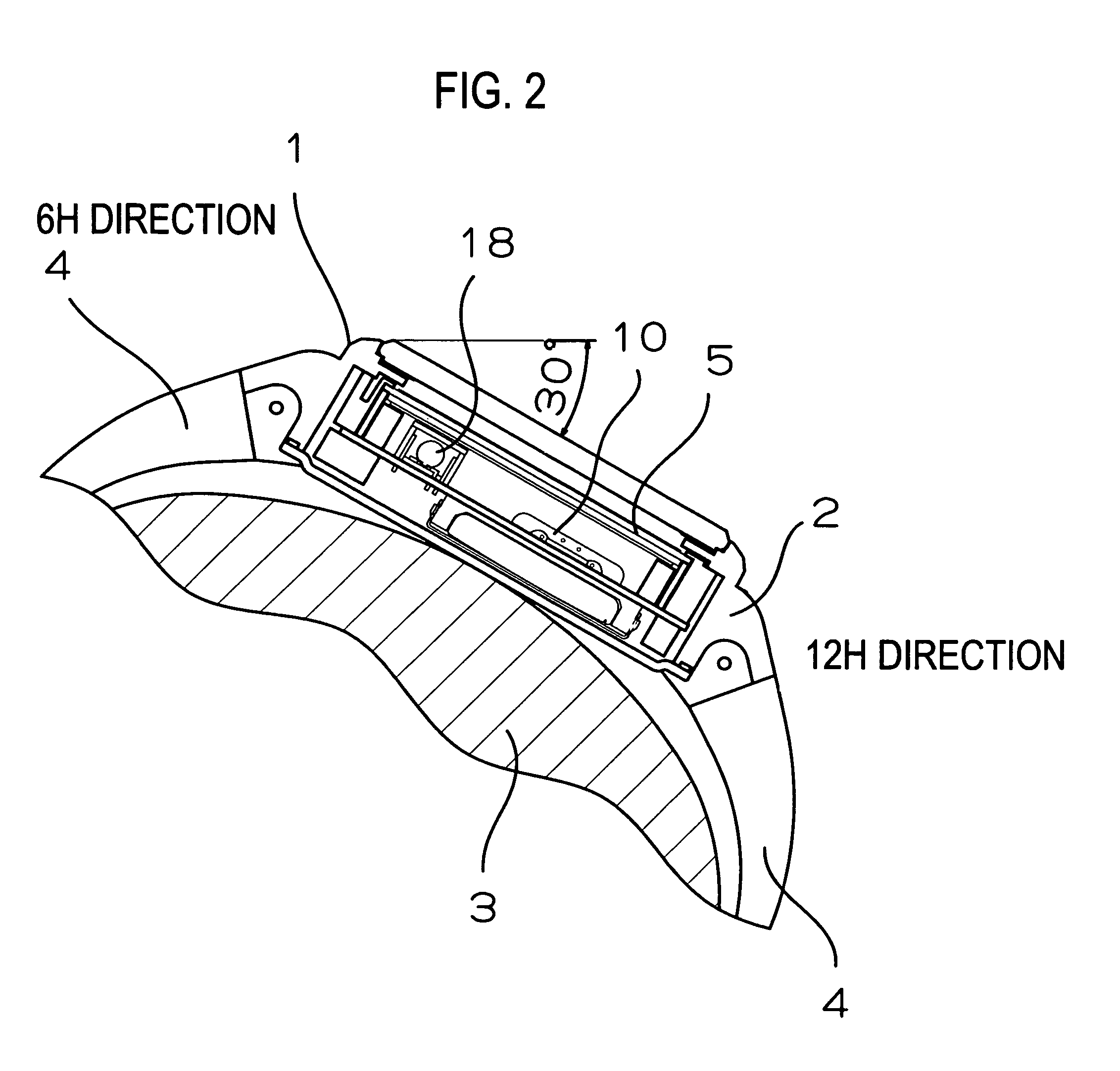
[0030]As shown in FIG. 1 which is the plan view of the main part, FIG. 2 which is the sectional view of the main part having been shown under the state having been worn to the arm 3 of the user, and FIG. 4 of the block circuit, an electronic pedometer of the invention is one having been constituted by adding the pedometer function'to the electronic timepiece, and is an electronic timepiece with a step number measurement function, in which the timepiece band 4 has been attached to the timepiece main body 1.

[0031]The timepiece main body 1 has the timepiece case 2, the signal processing part 10 accommodated in the timepiece case 2, the acceleration sensor 17, and the slant sensor 18. The acceleration sensor 17 senses the swing of the arm during the walk of the user and the vibration exerted on the arm at the walk time, as the change in acceleration. When the electronic pedometer 50 has been slanted to the previously set angle, the slant sensor 18 outputs the slant signal showing the fa...


PUM


Abstract

To provide an electronic pedometer in which there is adapted such that a step number is counted by a walk motion of a user, and the step number is not counted by a motion other than a walk of the user. An electronic pedometer has a timepiece case, a signal processing part having been accommodated in the timepiece case, and an acceleration sensor and a slant sensor, which have been accommodated while holding their horizontal states. The signal processing part judges, in a case where the slant sensor has outputted a horizontality signal, whether or not an acceleration signal, that the slant sensor has generated in a horizontality time till a time at which it has thereafter outputted a slant signal, is a true walk signal, when there has been judged to be the true walk signal, it performs a walk addition and, when there has been judged not to be the true walk signal, it performs a signal processing so as not to perform the walk addition.

Description

BACKGROUND OF THE INVENTION[0001]1. Field of the Invention[0002]The present invention relates to an electronic pedometer which has an acceleration sensor as a walk sensor, and which is attached to an arm of a user by a band.[0003]2. Description of the Prior Art[0004]An electronic pedometer disclosed in JP-A-2005-309693 has an acceleration sensor as a walk sensor outputting a walk signal corresponding to a walk by detecting the walk of a user, a step number calculation means calculating a step number of the user on the basis of the walk signal, and a belt for attaching the acceleration sensor to a wrist of the user. The acceleration sensor is disposed in an electronic pedometer case such that its sensitivity shaft is located in a predetermined angle range with respect to a longitudinal direction of the belt. The “predetermined angle range” means that the sensitivity shaft of the acceleration sensor exists in a range from 90 degrees to less than 30 degrees counterclockwise with respec...

Claims


Application Information

Patent Timeline
Patent Type & Authority Patents(United States)
IPC IPC(8): G01C22/00
CPCG01C22/006G06M7/00
Inventor FUJIWARA, TOSHIYUKI
Owner SEIKO INSTR INC
Learn More