
HVAC twinning control

Active Publication Date: 2008-05-27
COPELAND COMFORT CONTROL LP
View PDF2 Cites 8 Cited by
  • Summary
  • Abstract
  • Description
  • Claims
  • Application Information

AI Technical Summary

Problems solved by technology

This different pressure condition can cause problems if one unit's blower operation depends on a safety switch, or a different time delay period than the other unit.

Method used


Image

  • HVAC twinning control
  • HVAC twinning control
  • HVAC twinning control

Examples


Embodiment Construction

[0015]The following description of the various embodiment(s) is merely exemplary in nature and is in no way intended to limit the invention, its application, or uses.

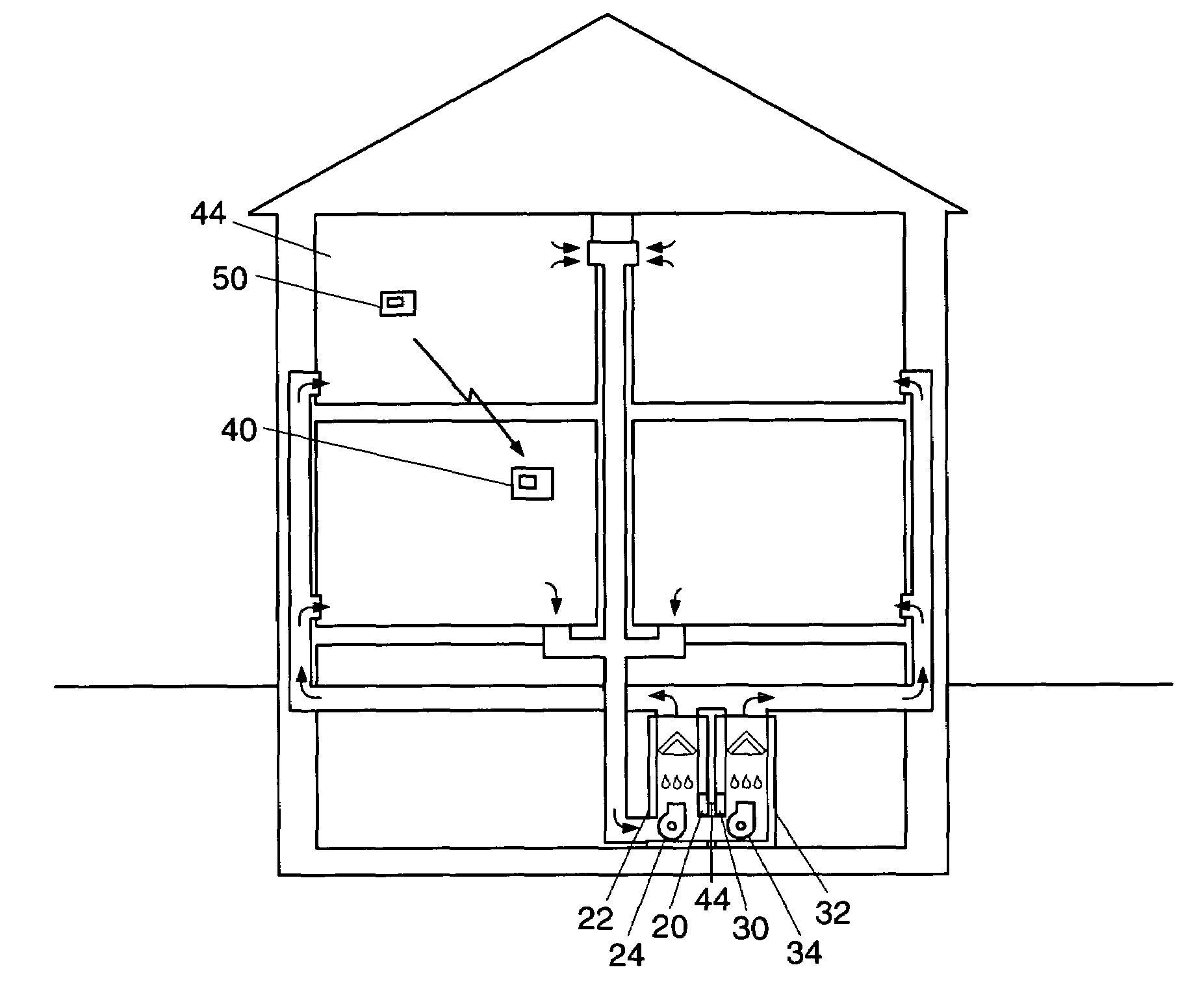
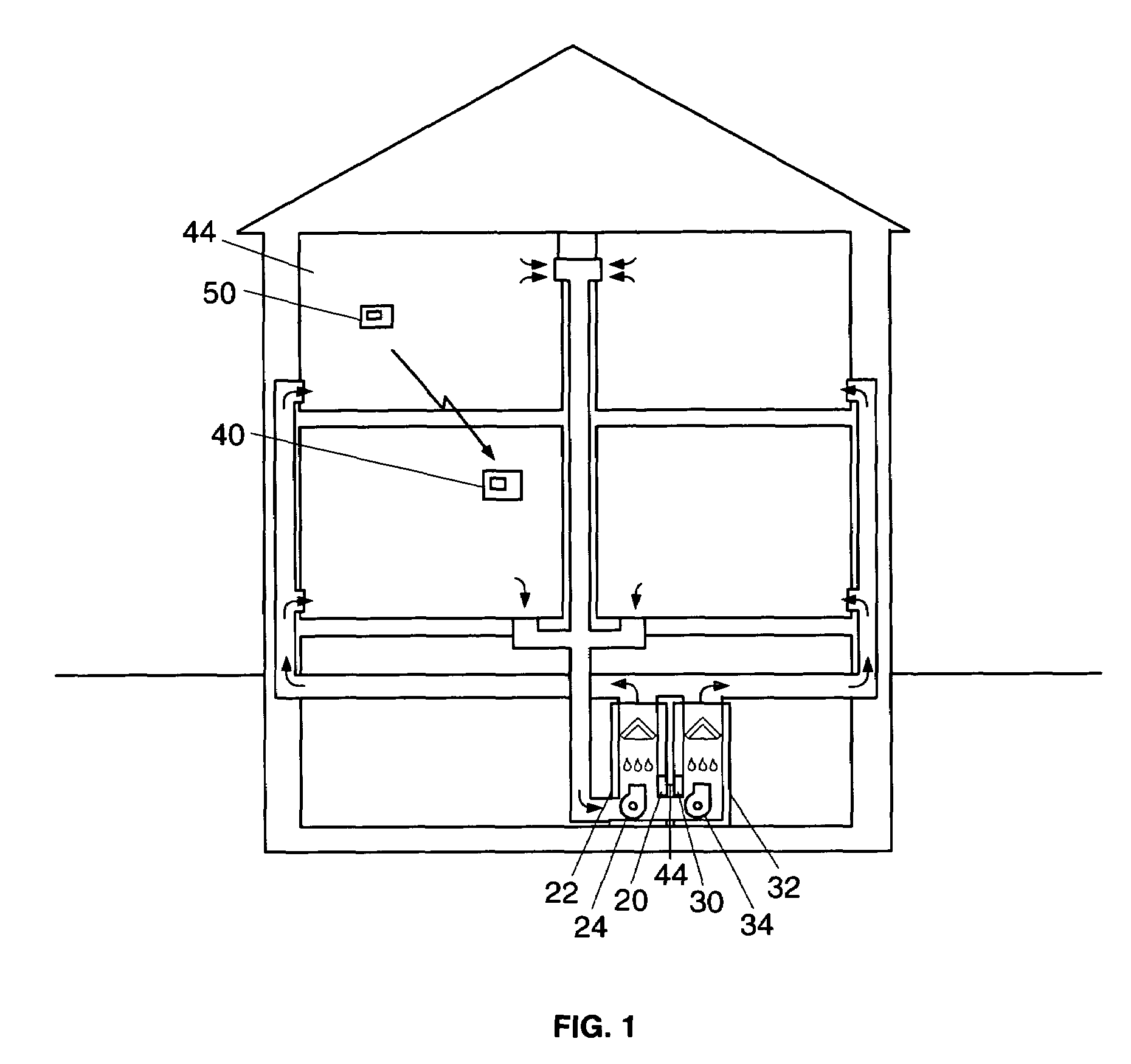
[0016]In one exemplary embodiment shown in FIG. 1, a control 20 for controlling a first HVAC unit 22 is provided that communicates with a like control 30 for controlling a second HVAC unit 32. The HVAC units 22 and 32 may be a heating, cooling, air-conditioning, or other temperature control apparatus, and preferably are coupled to a common shared duct. Each of the controls 20 and 30 provide an interface between a thermostat 40 in the space 42 and each of the HVAC units 22 and 32. The thermostat 40 accordingly sends signals to both HVAC controls 20 and 30 for initiating heating or cooling operation for a controlled space 42 such as a building. The twinning control may be used to control any number of HVAC units, but is described herein as controlling first and second HVAC units 22 and 32.

[0017]The first HVAC unit 22 incl...


PUM


Abstract

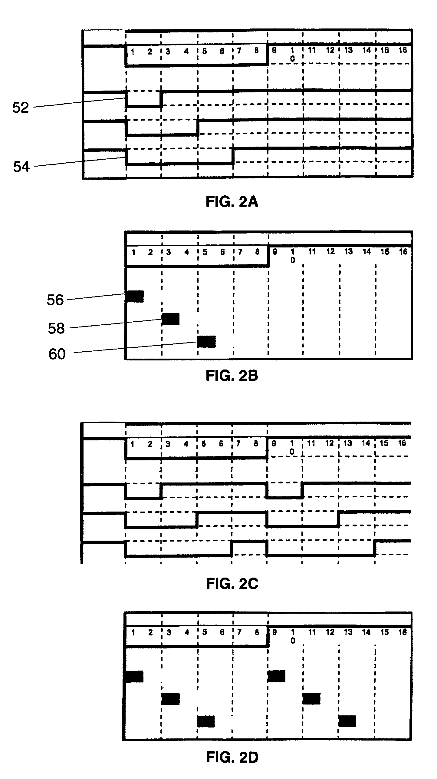
A control is provided for a first HVAC unit that is coupled to a common duct shared with at least one other HVAC unit. The control comprises a twinning connection for communication with at least a second control of another HVAC unit, and a voltage signal applied to the twinning connection. The control further comprises a switching means for switching the voltage signal to ground. A microcomputer for monitoring the twinning connection and for controlling the switching means is configured to actuate the switching means to switch the voltage at the twinning connection to ground for a predetermined time period to communicate a blower speed for the first HVAC unit. The microcomputer monitors the twinning connection to sense the duration that the voltage at the twinning connection is being conducted to ground, and responsively controls the speed of the first HVAC blower according to the prescribed blower speed corresponding to the sensed duration.

Description

[0001]The present invention relates generally to controllers used in temperature controlling systems such as HVAC (heating, ventilating, air-conditioning) systems. More specifically, the invention relates to an interface such as a twinning control for controlling the operation of two heating / cooling appliances such as HVAC units.BACKGROUND OF THE INVENTION[0002]Certain large homes require more heating or cooling than can be provided by a single residential HVAC unit. Instead of installing a larger commercial HVAC unit, installers may install two residential furnaces side by side with shared common ducting. This effectively increases the amount of heat that can be distributed into the home. Both furnaces operate from one thermostat, and ideally operate in the same mode at the same time. Such an arrangement is referred to as a twinned system. One aspect of a twinned system is that the circulator blowers should operate at the same speed. If one HVAC system operates its blower at a diff...

Claims


Application Information

Patent Timeline
Patent Type & Authority Patents(United States)
IPC IPC(8): F25B7/00
CPCF24F11/0009F24F11/0079F24F2011/0061Y02B30/746F24F11/30F24F11/63F24F11/77Y02B30/70
Inventor ZIKES, BRADLEY C.
Owner COPELAND COMFORT CONTROL LP
Learn More