Battery capacity measuring and remaining capacity calculating system

a technology of remaining capacity and measuring capacity, which is applied in the direction of engines, machines/engines, instruments, etc., can solve the problems of battery over-discharge, difficult to properly control the charging of the battery, and difficult to measure the current with the circuit fully open, so as to achieve the effect of calculating the remaining capacity quickly

Inactive Publication Date: 2003-09-16
TOYOTA JIDOSHA KK +1
View PDF20 Cites 111 Cited by
  • Summary
  • Abstract
  • Description
  • Claims
  • Application Information

AI Technical Summary

Benefits of technology

Owing to the above features, the open-circuit voltage of the battery is used to calculate the remaining capacity. The remaining capacity can therefore be calculated quickly. Moreover, after the fully-charged state judging means included in the fully-charged state judging system judges that the battery is fully-charged, when it is judged that the index of polarization falls within the range of index vales permitting stabilization of the open-circuit voltage of the battery, the relationship between the remaining capacity and open-circuit voltage established based on the degree of deterioration of the battery is learned. The remaining capacity is calculated by referencing the result of the learning using the open-circuit voltage of the battery. Consequently, the remaining capacity can be calculated highly precisely, irrespective of the deterioration of the battery.
In the aspect o

Problems solved by technology

In contrast, when the battery capacity is insufficient, the adjusting voltage is raised for fear the battery may be over-discharged.
This makes it hard to properly control charging of the battery.
It is therefore hard to measure the current with the circuit fully open.
The dark current flowing with the engine stopped cannot always be estimated correctly.
Thus, there is a fear that an error in a detected charging/discharge current may get larger.
However, the conventional remaining capacity calculating system cannot estimate the degree of pola

Method used


Image

  • Battery capacity measuring and remaining capacity calculating system
  • Battery capacity measuring and remaining capacity calculating system
  • Battery capacity measuring and remaining capacity calculating system

Examples


embodiments 1 and 2

, in which the second mode of the present invention is implemented, will be described in conjunction with the drawings below.

embodiment 1

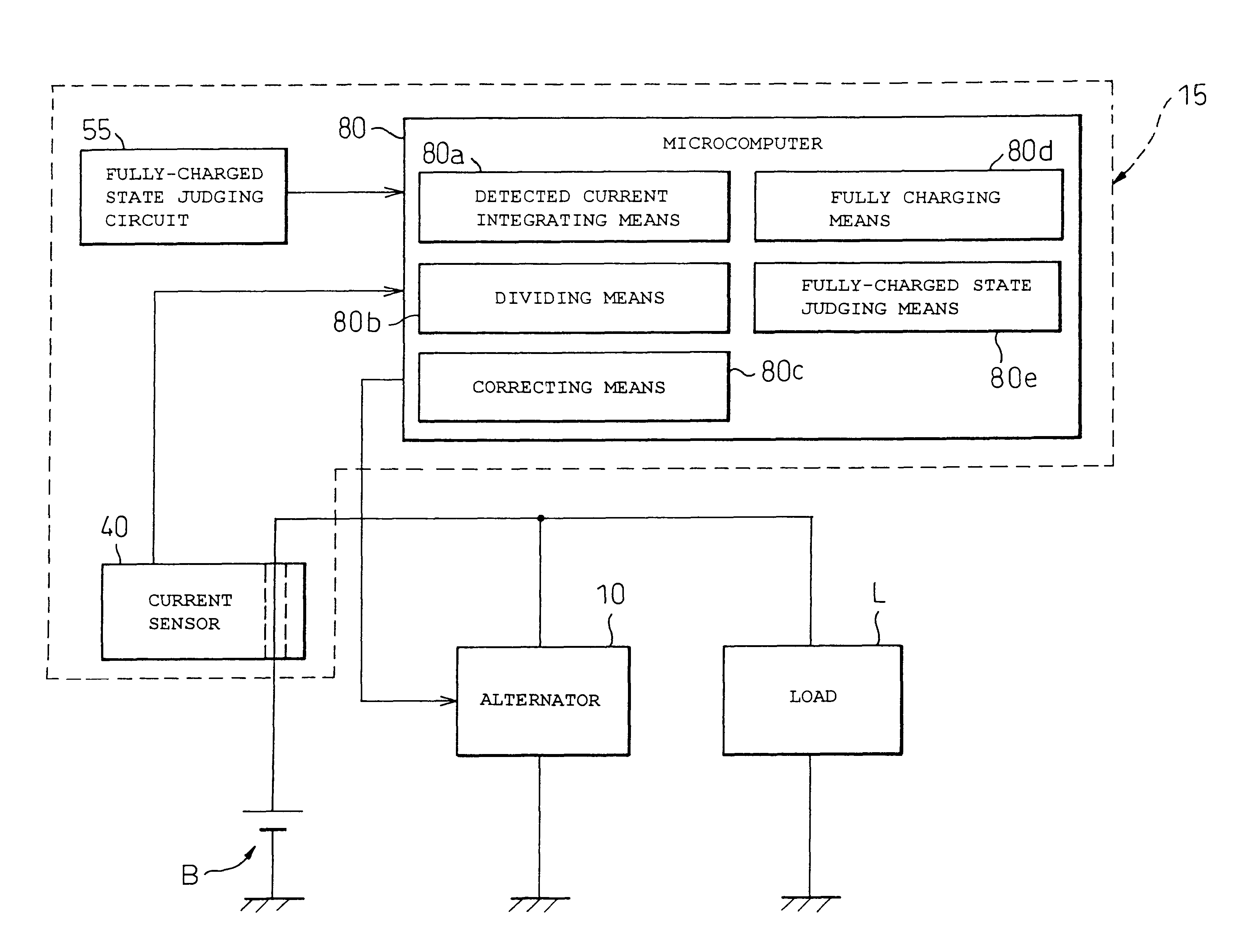
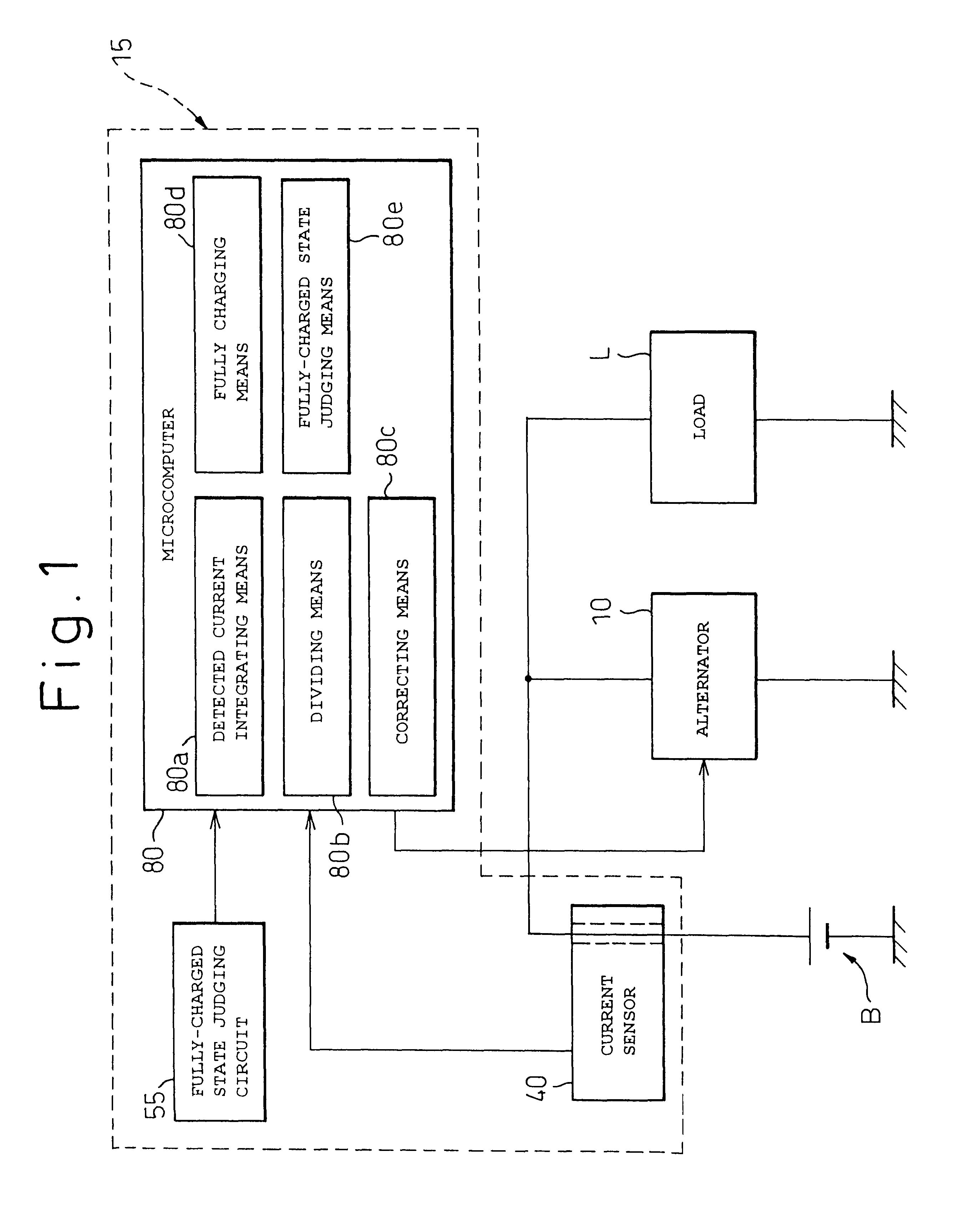
FIG. 4 shows an example in which the present invention is implemented in an automatic engine stopping / starting system for vehicles. A vehicle (automobile) includes, as shown in FIG. 4, a generator (alternator) 10, a rectifier 20 and a regulator 30. The alternator 10 is driven by an engine E of the automobile. The alternator 10 then generates ac power and applies an ac voltage. The rectifier 20 rectifies the ac voltage applied from the alternator 10, produces a rectified voltage, and applies the rectified voltage to a battery B and the regulator 30. The regulator 30 controls the output of the alternator 10 under the control of a microcomputer 80A, that will be described later, so that the output voltage will not be equal to or higher than an upper limit.

Moreover, the automatic engine stopping / starting system includes a current sensor 40, a voltage sensor 50, a magnitude-of-pedal depression sensor 60, and a vehicle speed sensor 70. The current sensor 40 detects a charging current or a...

embodiment 2

Next, Embodiment 2 in which the second mode of the present invention is implemented will be described in conjunction with FIG. 8 to FIG. 12. FIG. 8 shows an example 1 in which the present invention is implemented in a motor-generator control system for automobiles. An automobile includes a motor-generator (MG) 10A. The MG 10A is driven by an engine E and thus generates power or assists the engine E. An inverter 20A controls the power generated by the MG 10A so as to charge the battery B described in relation to Embodiment 1. Moreover, the inverter 20A controls power supplied from the battery B and feeds the power to the load L described in relation to Embodiment 1.

A motor-generator (MG) control circuit 90A is controlled by an engine control unit ECU 90B under the control of a microcomputer 80B, and controls the inverter 20A. The engine control unit ECU 90B not only controls the MG control-circuit 90A but also controls the engine

The microcomputer 80B runs a main control program and a...


PUM


Abstract

A battery capacity measuring device in accordance with the present invention has a fully-charged state detector (80e), a detected current integrator (80a), a divider (80b), and a corrector (80c) incorporated in a microcomputer (80). The fully-charged state detector detects that a battery is fully charged. The detected current integrator integrates current values that are detected by a current sensor during a period from the instant the battery is fully charged to the instant it is fully charged next. The divider divides the integrated value of detected current values by the length of the period. The corrector corrects a detected current using the quotient provided by the divider as an offset. Furthermore, a remaining battery capacity calculating system comprises a voltage detecting unit (50), a current detecting unit (40), an index calculating unit, a control unit, and a calculating unit. The voltage detecting unit detects the voltage at the terminals of a battery. The current detecting unit detects a current flowing through the battery. The index calculating unit calculates the index of polarization in the battery according to the detected current. The control unit controls the output voltage of an alternator so that the index of polarization will remain within a predetermined range which permits limitation of the effect of polarization on the charged state of the battery. When the index of polarization remains within the predetermined range, the calculating unit calculates the remaining capacity of the battery according to the terminal voltage of the battery, that is, the open-circuit voltage of the battery.

Description

The present invention relates to a battery capacity measuring and remaining capacity calculating system. More particularly, the present invention is concerned with a battery capacity measuring device for vehicle batteries, a remaining capacity calculating system for vehicle batteries, an automatic engine stopping / starting system for vehicles based on a remaining battery capacity, an electrical rotating machine control system for vehicles based on remaining battery capacity, and a fully-charged state judging system for vehicle batteries.Background Art Relating to the First Mode of the Present InventionA battery mounted in a vehicle is used as a power supply that supplies power to a starter for an engine and other accessories. The battery is charged from time to time by means of a generator that operates with power exerted by an internal combustion engine. A battery capacity measuring device measures a current battery capacity, and the generator is controlled based on the detected bat...

Claims


Application Information

Patent Timeline
IPC IPC(8): G01R35/00G01R31/36H02J7/14H02J7/00G01R31/00
CPCG01R31/3613G01R31/3624G01R31/3648G01R35/005H02J7/0078H02J7/1461G01R31/006G01R31/361H02J2007/0049H02J2007/005Y02T10/7005F02N11/0825F02N2200/062F02N2200/063G01R31/3832G01R31/3842G01R31/3828H02J7/0049H02J7/0048H02J7/00714Y02T10/40H02J7/14Y02T10/70H02J7/005
Inventor OHKUBO, NAOHIKOKISHIDA, SHINJIITO, SHINICHIKAWAI, TOSHIYUKIKIKUCHI, KATSUHIDEKIKUCHI, TETSURO
Owner TOYOTA JIDOSHA KK
Why Eureka
Try Eureka