Knitted sensor

a sensor and knitted technology, applied in knitting, warp knitting, weaving and other directions, can solve the problems of reducing the viable range of applications of the sensor, affecting the sensitivity of mechanical interactions at different locations, and the frequency of undesirable triggering of the sensor may be unacceptable for some applications,

Inactive Publication Date: 2008-05-27
WEARABLE TECH LTD
View PDF16 Cites 56 Cited by
  • Summary
  • Abstract
  • Description
  • Claims
  • Application Information

AI Technical Summary

Benefits of technology

[0010]According to an aspect of the present invention, there is provided a sensor comprising: a first knitted conductive textile plane, a second conductive textile plane, and an intermediate separating plane penetrable by the first knitted conductive textile plane to allow the first conductive textile plane and the second conductive textile plane to make electrical contact under a mechanical interaction; the intermediate separating plane defines structural endpoints extending towards the first conductive textile layer that are boundary vertices of a virtual polygonal aperture window and from which the first knitted conductive textile plane deforms towards the second conductive textile plane under a mechanical interaction; wherein: the first knitted conductive textile plane has conductive yarn knitted to form a repeating pattern of stitches each comprising a stitch looping portion SLP having a looping portion footprint LPF, the separating plane defines virtual polygonal aperture windows AW having an aperture window footprint AWF, and at least one looping portion footprint LPF is wholly containable within at least one aperture window footprint AWF.

Problems solved by technology

A problem with this type of textile sensor is that the frequency of undesirable triggering of the sensor may be unacceptable for some applications.
Undesirable triggering may be caused by bending or flexing of the sensor, or by internal forces within the sensor arising from deviations from the sensor pattern during manufacture, creases or other set within one or more layers accrued during manufacture or use of the sensor.
This arrangement is not suitable for applications of touch sensors in which flexibility is required, and the frame may impart unacceptable variations in sensitivity to mechanical interactions at different locations across the sensing area.
The cost of production of this more complex sensor, however, is considered to diminish the viable range of applications of the sensor.

Method used


Image

  • Knitted sensor
  • Knitted sensor
  • Knitted sensor

Examples


Embodiment Construction

FIG. 1

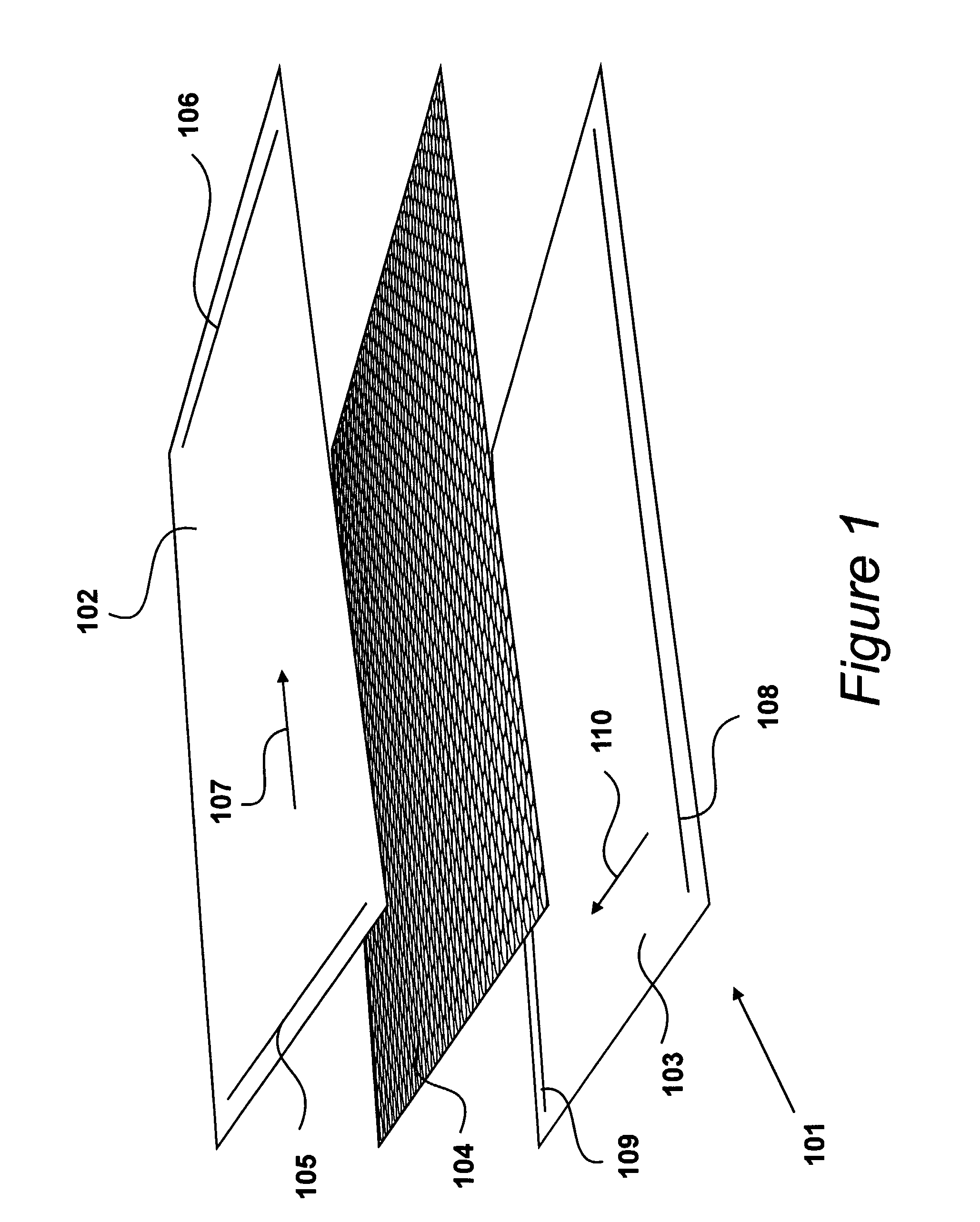
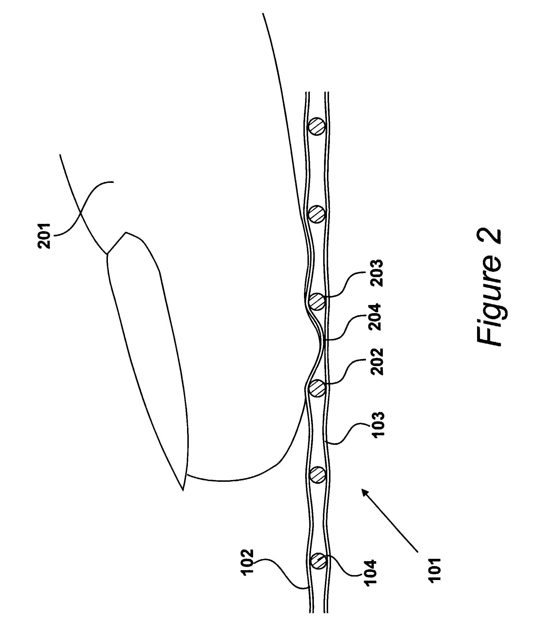
[0031]An exploded view of a position sensor is shown in FIG. 1. Sensor 101 utilises a three layer construction including a first electrically conducting layer 102, a second electrically conducting layer 103 and an intermediate separating layer 104, in this example a mesh fabricated from electrically insulating material, disposed between the two conductive textile layers 102, 103.

[0032]The electrically conducting layers are preferably in the form of fabrics machined from a mixture of electrically conducting fibres and insulating fibres. An example of a fabric of this type is disclosed in International Patent Publication No. WO 00 / 72240.

[0033]First electrically conducting layer 102 is provided with a first pair of conducting members 105, 106, with one extending along each edge of a first pair of opposed edges of the layer. In response to an electrical potential applied between these conducting members 105, 106 electrical current may flow across first layer 102 in a direction ind...


PUM


Abstract

A sensor having a three layer construction comprising a first knitted conductive textile plane, a second conductive textile plane and an intermediate separating plane penetrable by the first knitted conductive textile plane to allow the first conductive textile plane and the second conductive textile plane to make electrical contact under a mechanical interaction. The intermediate separating plane defines structural endpoints from which the first knitted conductive textile plane deforms towards the second conductive textile plane under a mechanical interaction. The first knitted conductive textile plane has conductive yarn knitted to form a repeating pattern of stitches each comprising a stitch looping portion SLP having a looping portion footprint LPF. Within the sensor, there is at least one of a plurality of described dimensional relationships between stitches of the first knitted conductive textile plane and structural endpoints of the intermediate separating plane.

Description

BACKGROUND OF THE INVENTION[0001]1. Field of the Invention[0002]The present invention relates to improving the uniformity of the response of a sensor to a mechanical interaction, in particular to improving the uniformity of the sensitivity of a sensor having at least one conductive textile knitted layer.[0003]2. Description of the Related Art[0004]In many applications of manually operable touch sensors, the sensor is required to be flexible and sensitive to applied pressure within predetermined tolerances. A type of fabric touch sensor having a three layer construction comprises two outer conductive textile layers and a central separator layer defining a plurality of apertures. The separator layer is configured to space the conductive textile layers apart when no pressure is applied to the sensor, and to allow electrical contact between the layers under a mechanical interaction.[0005]A problem with this type of textile sensor is that the frequency of undesirable triggering of the se...

Claims


Application Information

Patent Timeline
Patent Type & Authority Patents(United States)
IPC IPC(8): D04B1/22G06F3/033H01H3/14
CPCH01H3/141H01H2203/0085H01H2203/01Y10T442/102Y10T442/40Y10T442/425Y10T442/45
Inventor SANDBACH, DAVID LEEBURKITT, JOHNWALKINGTON, STUART MARKCRISPIN, PHILLIPE GEORGES
Owner WEARABLE TECH LTD
Why Eureka
Try Eureka