Method and apparatus providing role-based configuration of a port of a network element

a network element and role-based configuration technology, applied in the field of network management, can solve the problems of manual process, manual record-keeping, manual intervention by an administrator, etc., and achieve the effect of not determining the information about which devices are connected to the ports in the cns

Active Publication Date: 2008-05-27
CISCO TECH INC
View PDF20 Cites 208 Cited by
  • Summary
  • Abstract
  • Description
  • Claims
  • Application Information

AI Technical Summary

Benefits of technology

[0080]As shown in block 310, a test is performed to determine whether the discovered information satisfies a particular rule. If not, then in block 312 a test is performed to determine whether other profiles are available for testing. If the test of block 312 is true, then control returns to block 308 and block 310 for processing of the other profiles. If the test of block 312 is negative, then in block 316 the then-current port is mapped to a default profile.
[0081]If a match occurs at block 310, then control transfers to block 314, in which the then-current port is mapped to a profile selected from among profile rules 130.

Problems solved by technology

The manual process is time-consuming and requires manual record-keeping.
Further, if an end station device is changed, a port connected to that device may require re-configuration to account for differences in the new end station device.
Currently, this requires manual intervention by an administrator, which is costly.
The Cisco Networking Services (CNS) solution from Cisco Systems, Inc. can discover information about the physical setup of modular routers including what kind of ports are present; however, CNS does not determine information about which devices are connected to the ports that it has discovered.
However, both of these approaches impose configuration challenges relating to proper configuration of the associated servers, and impose higher costs for servers on their users.
Further, while the IE2100 can dynamically create a configuration for a device based on the types of ports discovered, it cannot do so based on what devices are connected to the ports.
However, this approach does not discover devices that are connected to ports of the switch in the network, and does not determine what role is played by devices that are connected to ports of the switch.
The network administrator is required to use a separate manual process to perform any such discovery and role determination, with the associated burden of keeping appropriate records and responding to changes manually as the changes occur.
The approach also does not automatically apply a different configuration to each port based on determining the role of a connected device.
However, this approach does not establish a port configuration based on the type of device coupled to the port or the role played by the port with respect to the device.

Method used


Image

  • Method and apparatus providing role-based configuration of a port of a network element
  • Method and apparatus providing role-based configuration of a port of a network element
  • Method and apparatus providing role-based configuration of a port of a network element

Examples


Embodiment Construction

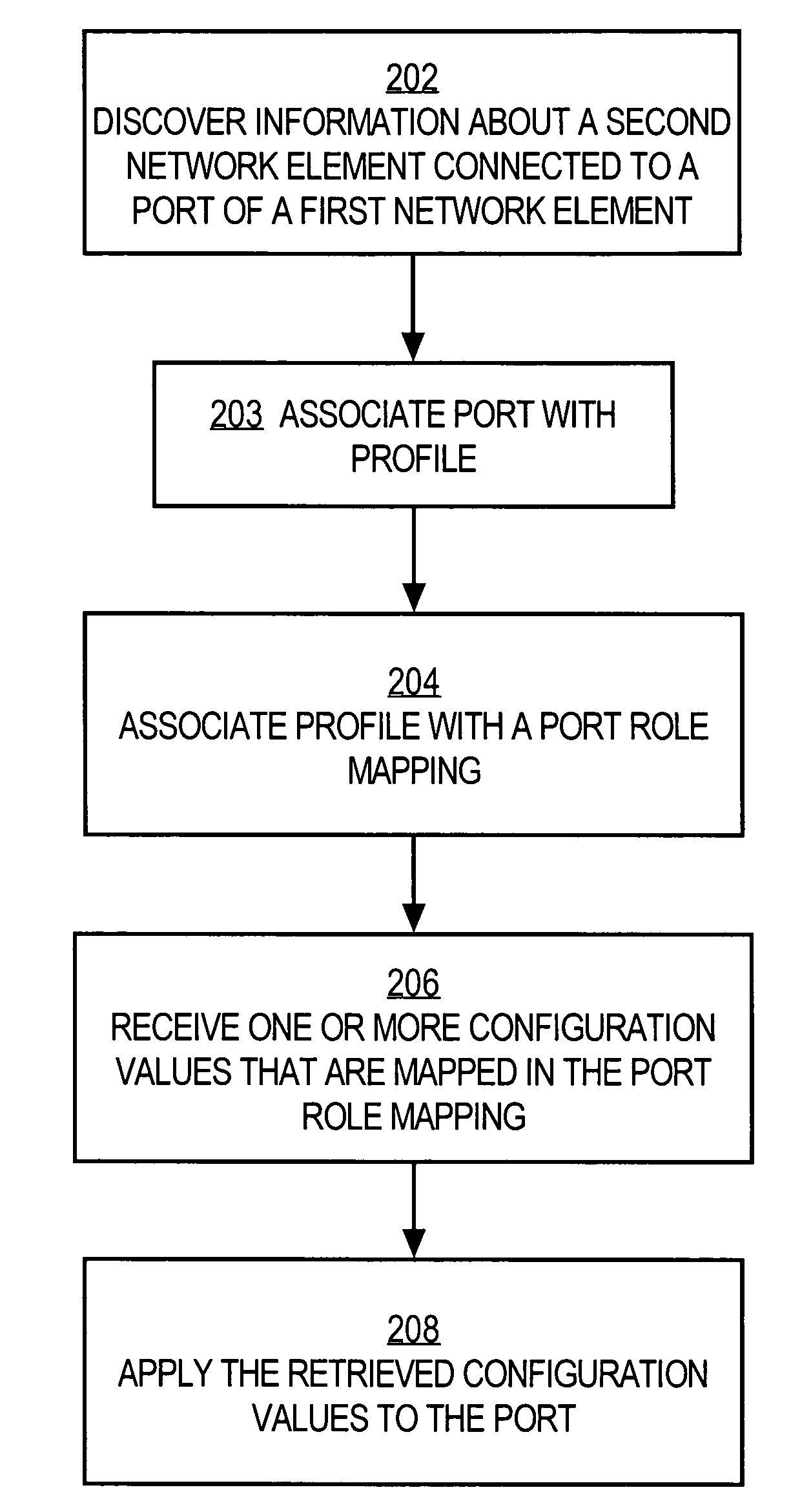
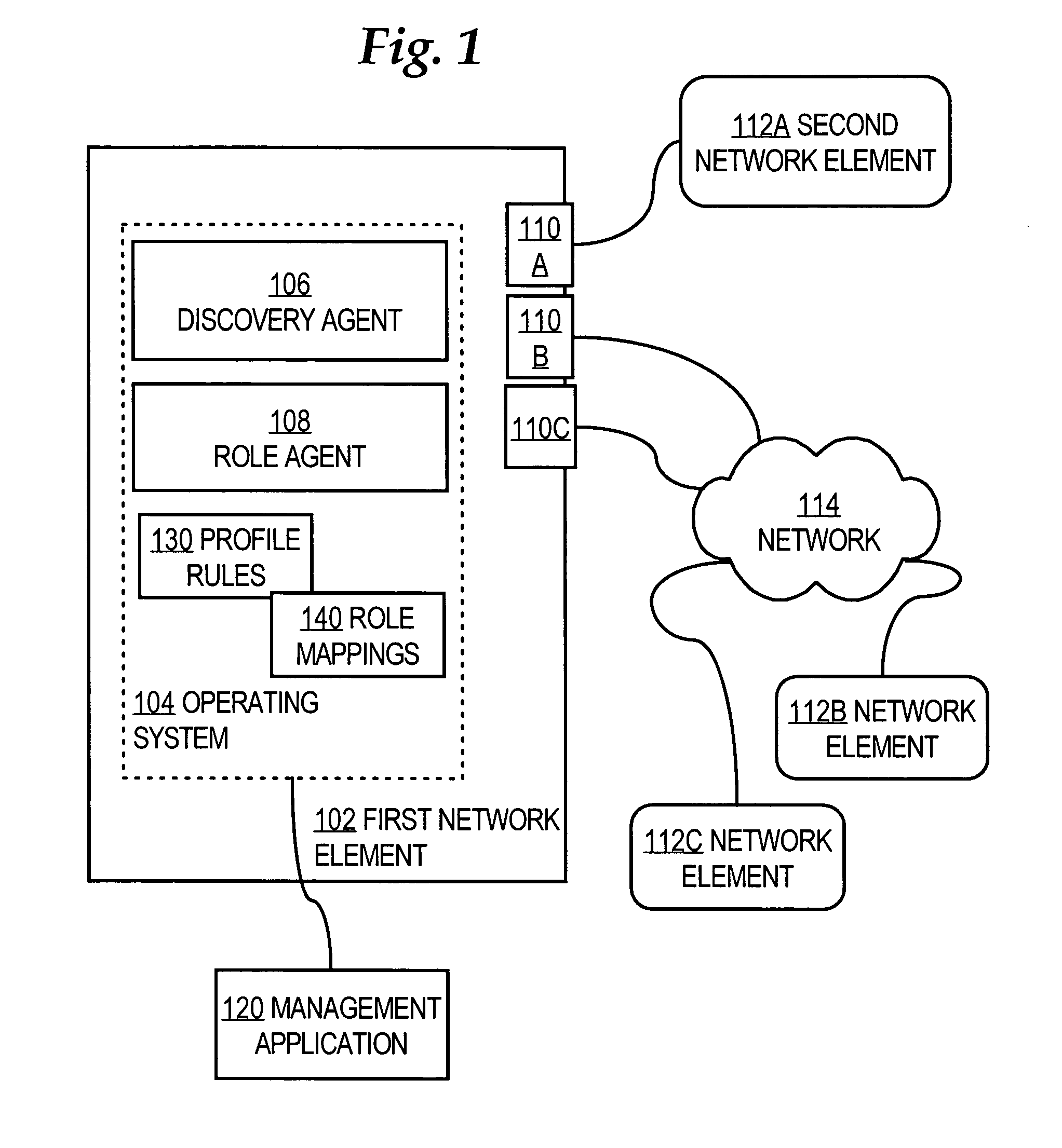
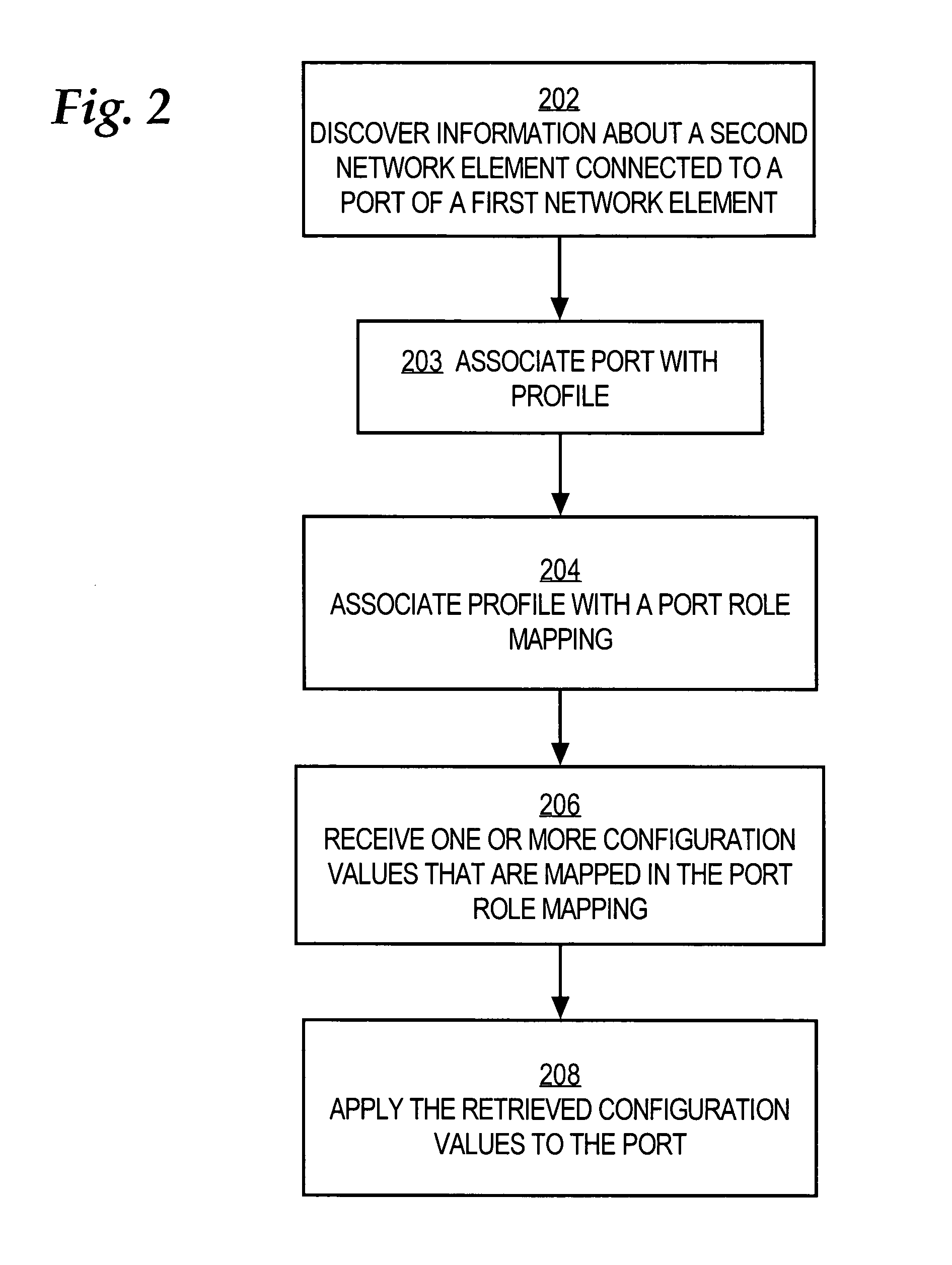
[0020]A method and apparatus providing role-based configuration of a port of a network element is described. In the following description, for the purposes of explanation, numerous specific details are set forth in order to provide a thorough understanding of the present invention. It will be apparent, however, to one skilled in the art that the present invention may be practiced without these specific details. In other instances, well-known structures and devices are shown in block diagram form in order to avoid unnecessarily obscuring the present invention.

[0021]Embodiments are described herein according to the following outline:[0022]1.0 General Overview[0023]2.0 Structural and Functional Overview[0024]2.1 Architecture[0025]2.2 Role-Based Configuration Approaches[0026]2.3 Complete Example[0027]2.4 Time of Execution[0028]2.5 Interaction with Management Applications and Other Solutions[0029]2.6 Applicability to Physical Ports and Logical Ports[0030]2.7 Failure Processing[0031]3.0 I...


PUM


Abstract

A method of automatically configuring a port of a network element comprises the steps of discovering information that identifies or describes a second network element that is coupled to a port of a first network element; associating the port with a port role definition selected from a plurality of port role definitions based on the discovered information; retrieving one or more configuration settings that are associated with the selected port role definition; and applying the one or more configuration settings to the port.

Description

FIELD OF THE INVENTION[0001]The present invention generally relates to network management. The invention relates more specifically to a method and apparatus providing role-based configuration of a port of a network element.COPYRIGHT NOTICE[0002]A portion of the disclosure of this patent document contains material which is subject to copyright protection. The copyright owner has no objection to the facsimile reproduction of the patent disclosure, as it appears in the Patent & Trademark Office patent file or records, but otherwise reserves all copyright rights whatsoever. Copyright© 2003 Cisco Systems, Inc.BACKGROUND OF THE INVENTION[0003]The approaches described in this section could be pursued, but are not necessarily approaches that have been previously conceived or pursued. Therefore, unless otherwise indicated herein, the approaches described in this section are not prior art to the claims in this application and are not admitted to be prior art by inclusion in this section.[0004...

Claims


Application Information

Patent Timeline
Patent Type & Authority Patents(United States)
IPC IPC(8): G06F3/00G06F13/12
CPCH04L41/0809H04L41/0853H04L41/12H04L41/0213
Inventor RIGGINS, CHRISBERL, STEVENANTEUNIS, DIRKSTAMLER, ARNOLD
Owner CISCO TECH INC
Why Eureka
Try Eureka