Single bore high flow junction plate

a high-flow junction plate, single-bore technology, applied in the direction of hose connection, borehole/well accessories, sealing/packing, etc., can solve the problem that the stab cannot typically be equipped with multiple seals, and the cost of such junction plates is increased

Active Publication Date: 2008-06-03
OCEANEERING INTERNATIONAL
View PDF8 Cites 25 Cited by
  • Summary
  • Abstract
  • Description
  • Claims
  • Application Information

AI Technical Summary

Problems solved by technology

The stabs cannot typically be equipped with multiple seals that can be engaged on an as-needed basis, and the junction plates rely on multiple, small-bore hydraulic couplers that are ganged together to create a sufficiently large flow path.
The use of such hydraulic couplers increases the cost of such junction plates.

Method used


Image

  • Single bore high flow junction plate
  • Single bore high flow junction plate
  • Single bore high flow junction plate

Examples


Embodiment Construction

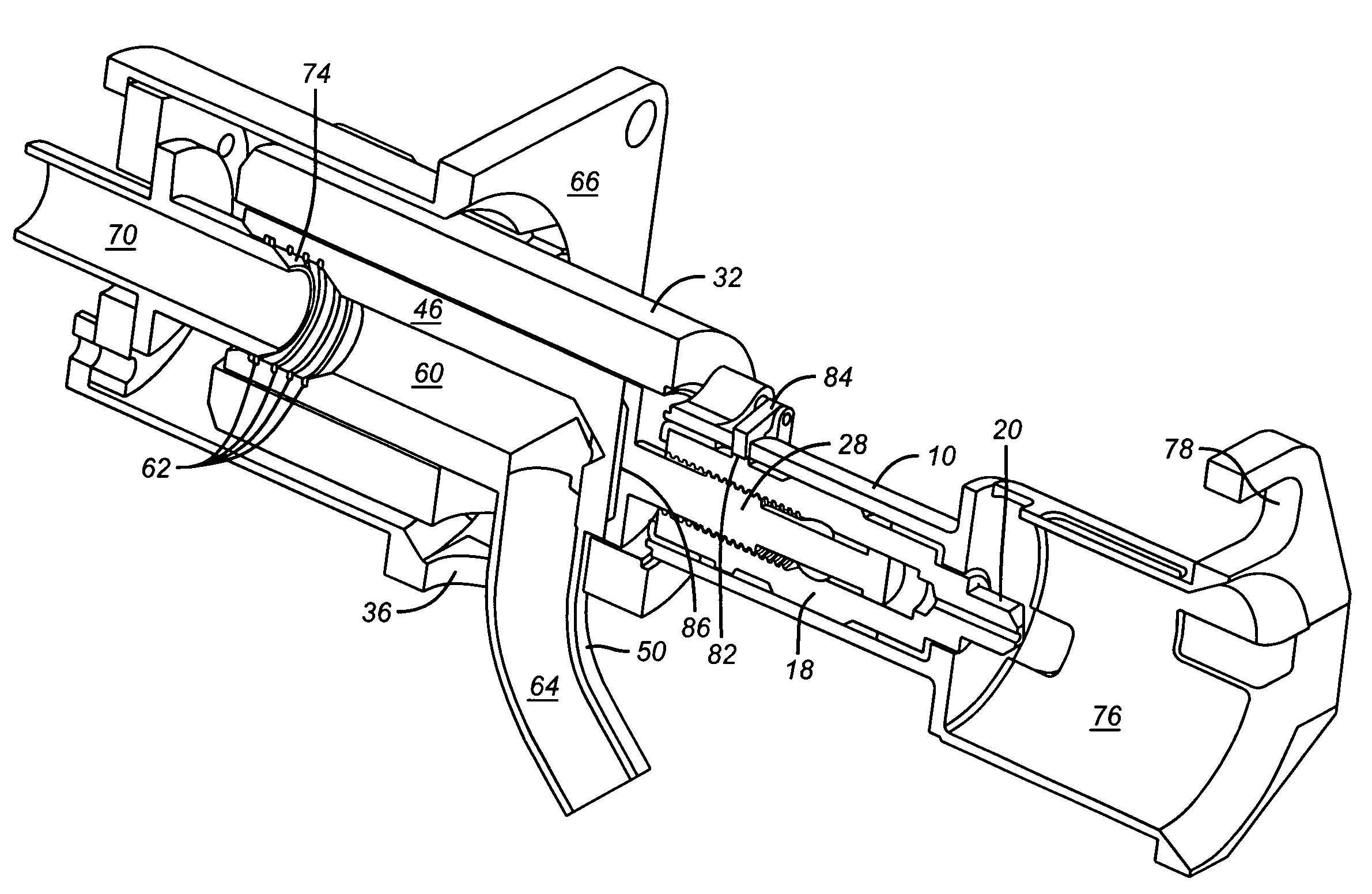
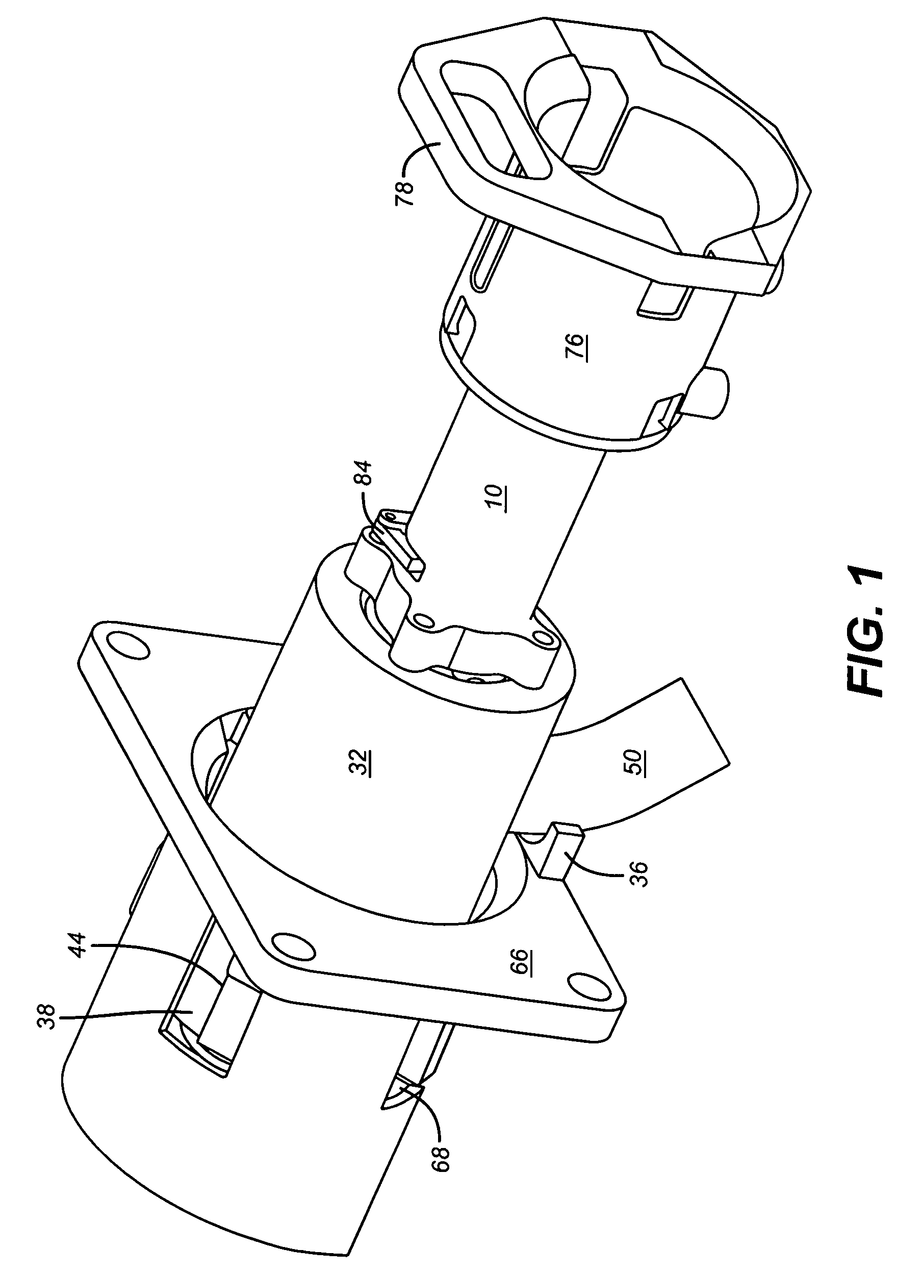
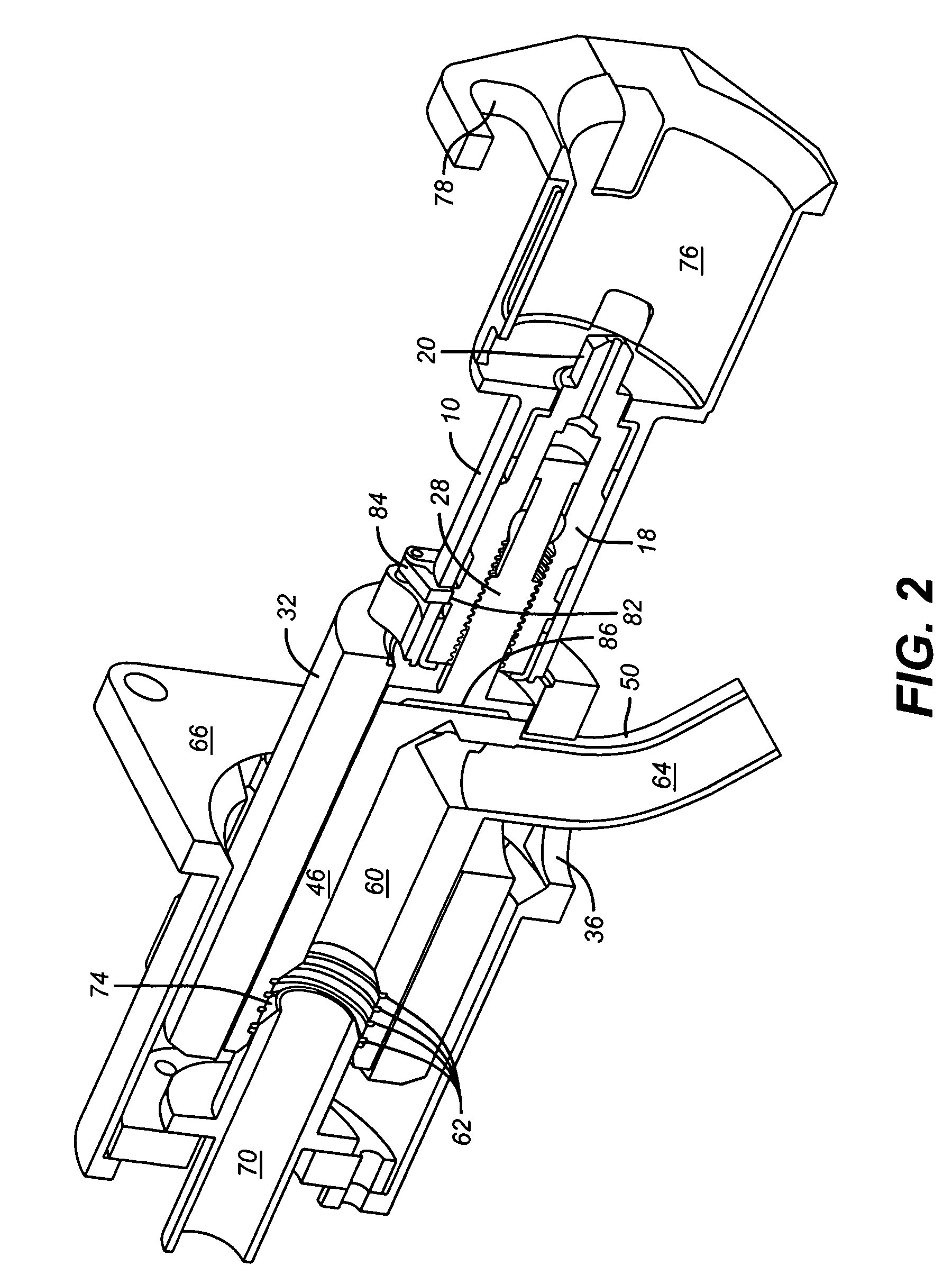
[0015]It is generally believed that gas injection into oil flow lines will become a more common practice. The disclosed inventions allow the connection of a gas source to the oil flow line to achieve that. An advantage is that the design of the disclosed inventions affords a large unobstructed flow path in a design that uses a very simple latching mechanism. Additionally, a preferred embodiment of the present invention utilizes a J-slot “lock”. Further, “replacement” seals can be “installed” simply by rotating the lead screw by a controlled amount.

[0016]Referring generally to the preferred embodiments depicted in FIGS. 1-3, a single port stab is an assembly that is connected to one end of a high flow line, typically a gas-injection line. In a preferred embodiment, an ROV engages the torque bucket using an ROV torque tool and the ROV “flies” the stab to the stab receptacle which is permanently mounted at the subsea gas injection point. The ROV rotates the torque tool, and consequentl...


PUM


Abstract

Described herein a single bore, high flow junction plate and flow line assembly adapted for use subsea. This junction plate may be adapted for use with a torque tool manipulated by a remotely operated vehicle (“ROV”).

Description

PRIORITY INFORMATION[0001]This application claims the benefit of U.S. Provisional Application No. 60 / 622,768, filed on Oct. 28, 2004.FIELD OF THE INVENTION[0002]The invention relates to junction plates. The invention more specifically relates to a single bore, high flow junction plate and flow line assembly adapted for use subsea. This invention may be adapted for use with a torque tool manipulated by a remotely operated vehicle (“ROV”).BACKGROUND OF THE INVENTION[0003]Junction plates are used subsea. The flow path through current junction plates is typically not straight and makes turns though perimeter port holes or flow paths. The stabs cannot typically be equipped with multiple seals that can be engaged on an as-needed basis, and the junction plates rely on multiple, small-bore hydraulic couplers that are ganged together to create a sufficiently large flow path. The use of such hydraulic couplers increases the cost of such junction plates.BRIEF DESCRIPTION OF THE DRAWINGS[0004]T...

Claims


Application Information

Patent Timeline
Patent Type & Authority Patents(United States)
IPC IPC(8): E21B7/12E21B41/04
CPCE21B41/0007
Inventor MCCOY, RICHARDCUNNINGHAM, MICHAELWATERS, C. CURTIS
Owner OCEANEERING INTERNATIONAL
Why Eureka
Try Eureka