Tracking attachment

a technology of tracking and attachment, applied in the direction of mechanical measuring arrangement, instruments, using mechanical means, etc., can solve the problems of significant inaccuracy and potential problems of tracking problems in vehicles, and achieve the effect of convenient, efficient, and accurate measurement and determination

Active Publication Date: 2008-06-10
VEHICLE SERVICE GROUP LLC
View PDF12 Cites 7 Cited by
  • Summary
  • Abstract
  • Description
  • Claims
  • Application Information

AI Technical Summary

Benefits of technology

[0009]In one embodiment, the tracking attachment broadly comprises an adjustment component; a bar component; one or more target components; an alignment component; one or more attachment components; a centering component; and a locking component. The adjustment component facilitates adjusting the position of the bar component, and takes the form of an adjustment ring including a partial disk presenting an arcing portion and a straight portion. The bar component facilitates supporting the target components in their proper positions for making the desired measurements of the vehicle's suspension, and takes the form of an elongated bar presenting first and second opposite ends, and a target mount at each end. The target components facilitate making the desired measurements of the vehicle's suspension, and take the form of retroreflective bar-coded targets. The alignment component facilitates leveling and aligning the tracking attachment, and takes the form of an alignment ring including a full disk presenting elongated leg adjusting slots on inwardly projecting tabs, and an elongated ring and bar adjusting slot having an arc shape corresponding to the arc of the disk. The attachment components facilitate maintaining the tracking attachment in its proper operating position relative to a wheel drum or hub of the vehicle, and take the form of legs, with each leg including a housing and a magnet and being removably and repositionably coupleable to a respective one of the elongated leg adjusting slots provided by the alignment ring. The centering component facilitates centering and positioning the tracking attachment in its proper operating position relative to the wheel drum or hub of the vehicle, and takes the form of a center pin including a cone end and a pointer end and which is slideably insertable through a through-hole in the bar and a through-hole in the adjustment ring. The locking component facilitates locking the adjustment component and the bar component in proper operating position relative to the alignment component, and takes the form of a locking knob which removably and repositionably engages both a through-hole in the adjustment ring and the elongated ring and bar adjusting slot provided by the alignment ring.
[0010]In addition to the aforementioned components, the tracking attachment further includes a pointer alignment block which facilitates aligning and associating the center pin with the adjustment ring and the bar. The center pin is slideably insertable through aligned though-holes in the bar, the adjustment ring, and the pointer alignment block. The pointer alignment block includes a bubble level to facilitate leveling the bar component.
[0012]Thus, it will be appreciated that the tracking attachment of the present invention provides a number of significant advantages, including, for example, facilitating convenient, efficient, and accurate measurement and determination of various alignment characteristics of a vehicle.

Problems solved by technology

Tracking problems can arise in vehicles as a result of Diamond damage or misalignment of the rear wheels. methods of checking tracking include, for example, attaching surveyor's string to a frame, suspension, or other component behind a rear tire; pulling the string across the tire, such that the string is just touching the outer front surface of the tire (i.e., such that the string is substantially parallel with the outer surface of the tire); extending the string to a point further forward on the vehicle, such as the cowl area, and measuring the distance between the string and the frame at that point.
Other methods for determining these and other alignment characteristics suffer from a number of problems and disadvantages, including, for example, that they can be cumbersome, inconvenient, or time-consuming to employ and that they can result in significant inaccuracy.

Method used


Image

  • Tracking attachment
  • Tracking attachment
  • Tracking attachment

Examples


Embodiment Construction

, below.

BRIEF DESCRIPTION OF THE DRAWING FIGURES

[0014]The present invention is described in detail below with reference to the attached drawing figures, wherein:

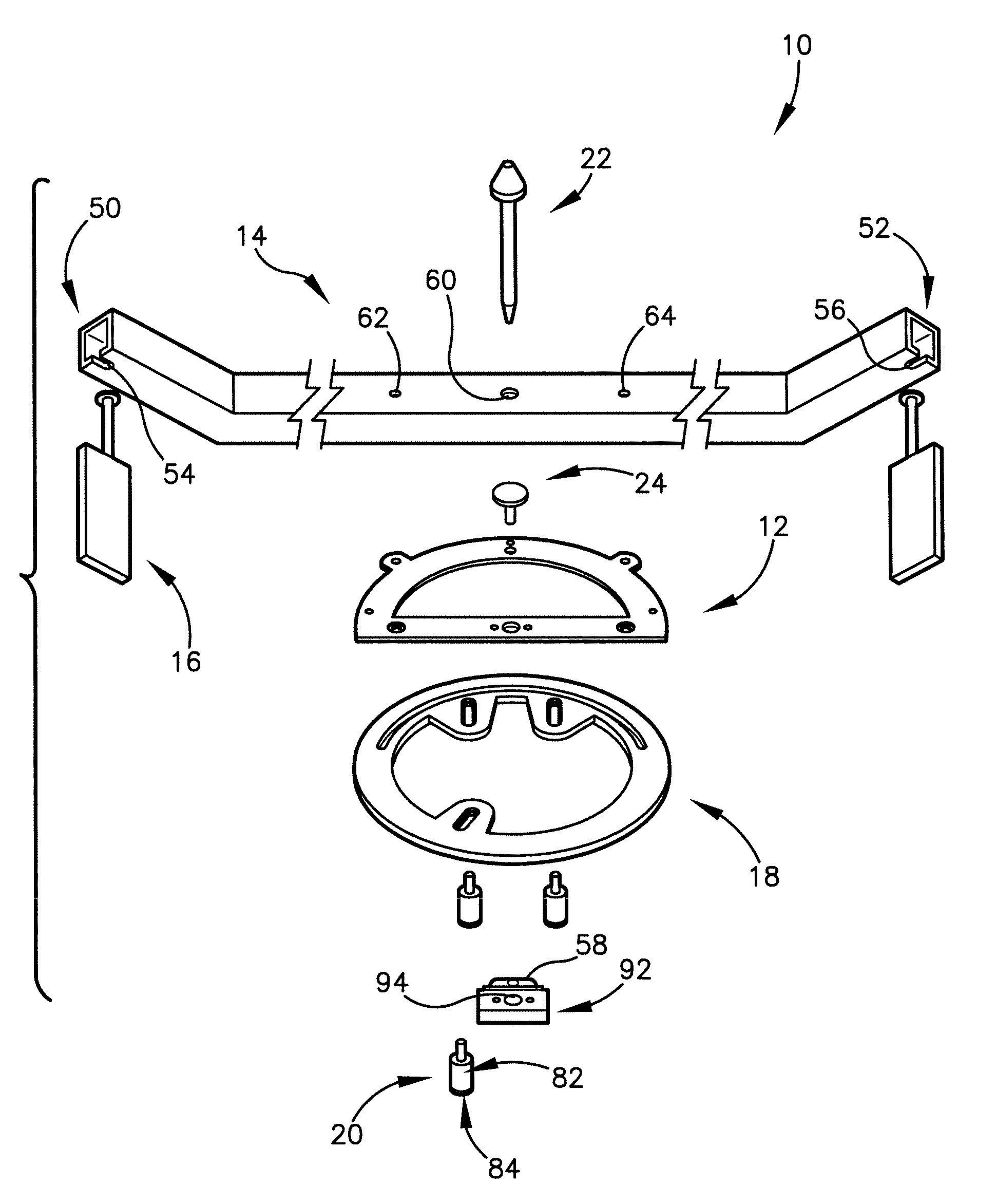
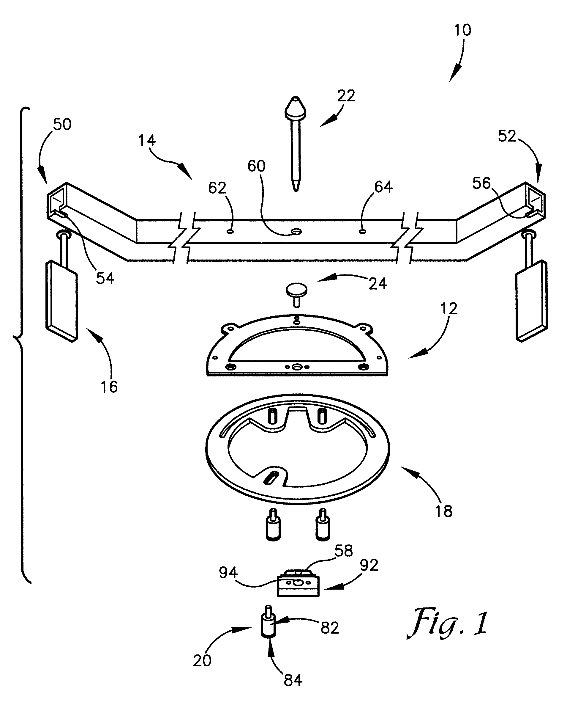
[0015]FIG. 1 is an exploded perspective view of an embodiment of the tracking attachment of the present invention;

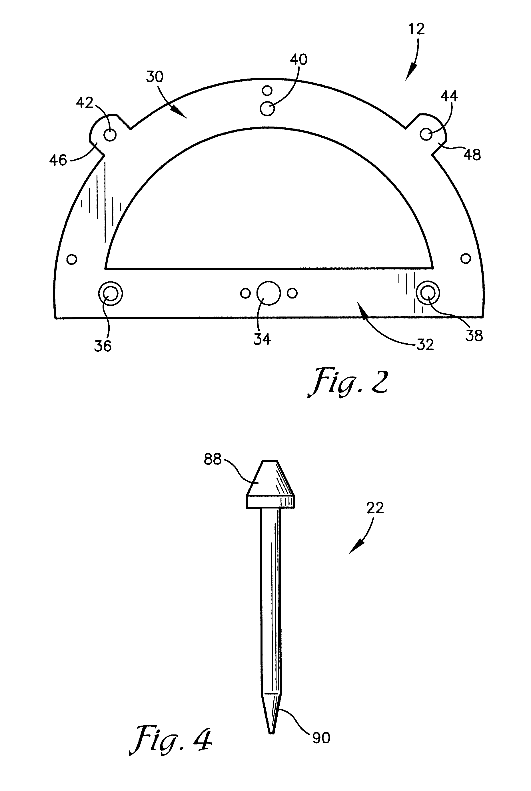
[0016]FIG. 2 is a plan view of an embodiment of an alignment component of the tracking attachment shown in FIG. 1;

[0017]FIG. 3 is a plan view of an embodiment of an adjustment component of the tracking attachment shown in FIG. 1;

[0018]FIG. 4 is an elevation view of an embodiment of a centering component of the tracking attachment shown in FIG. 1;

[0019]FIG. 5 is an elevation view of an alternative embodiment of the tracking attachment of the present invention;

[0020]FIG. 6 is a depiction of the tracking attachment of the present invention being used;

[0021]FIG. 7 is a flowchart showing a series of method steps involved in using the present invention;

[0022]FIG. 8 is a fragmentary cross-sectional elevation view of an ...


PUM


Abstract

A tracking attachment (10) adapted and operable to facilitate measuring the alignment characteristics of the rear suspension of a vehicle, including tracking (thrust angle), offset, toe-in and toe-out, and length characteristics. The tracking attachment (10) broadly comprises an adjustment component (12); a bar component (14); one or more target components (16); an alignment component (18); one or more attachment components (20); a centering component (22); and a locking component (24).

Description

RELATED APPLICATIONS[0001]The present U.S. non-provisional patent application claims priority benefit of an earlier-filed now abandoned U.S. provisional patent application of the same title, Ser. No. 60 / 731,680, filed Oct. 31, 2005. The identified provisional patent application is hereby incorporated by reference into the present non-provisional patent application.BACKGROUND OF THE INVENTION[0002]1. Field of the Invention[0003]The present invention relates to devices and methods for measuring one or more alignment characteristics of a rear suspension of a vehicle, such as tracking (thrust angle), offset, toe-in and toe-out, and length characteristics.[0004]2. Background of the Invention[0005]Tracking problems can arise in vehicles as a result of Diamond damage or misalignment of the rear wheels. methods of checking tracking include, for example, attaching surveyor's string to a frame, suspension, or other component behind a rear tire; pulling the string across the tire, such that th...

Claims


Application Information

Patent Timeline
Patent Type & Authority Patents(United States)
IPC IPC(8): G01B5/24
CPCG01B5/0025G01B5/255
Inventor KNOPIK, MIKEOLESEN, KEN
Owner VEHICLE SERVICE GROUP LLC
Why Eureka
Try Eureka