Self energized packer

a self-energized, packer technology, applied in the direction of sealing/packing, fluid removal, borehole/well accessories, etc., can solve the problems of limited design and extrusion of sealing elements, and achieve the effect of increasing contact pressur

Active Publication Date: 2008-06-17
BAKER HUGHES INC
View PDF37 Cites 172 Cited by
  • Summary
  • Abstract
  • Description
  • Claims
  • Application Information

AI Technical Summary

Problems solved by technology

These designs were still limited to the amount of swelling from the sealing element as far as the developed contact pressure against the surrounding tubular or wellbore.
In some designs there were also issues of extrusion of the sealing element in a longitudinal direction as it swelled radially.

Method used


Image

  • Self energized packer
  • Self energized packer
  • Self energized packer

Examples


Embodiment Construction

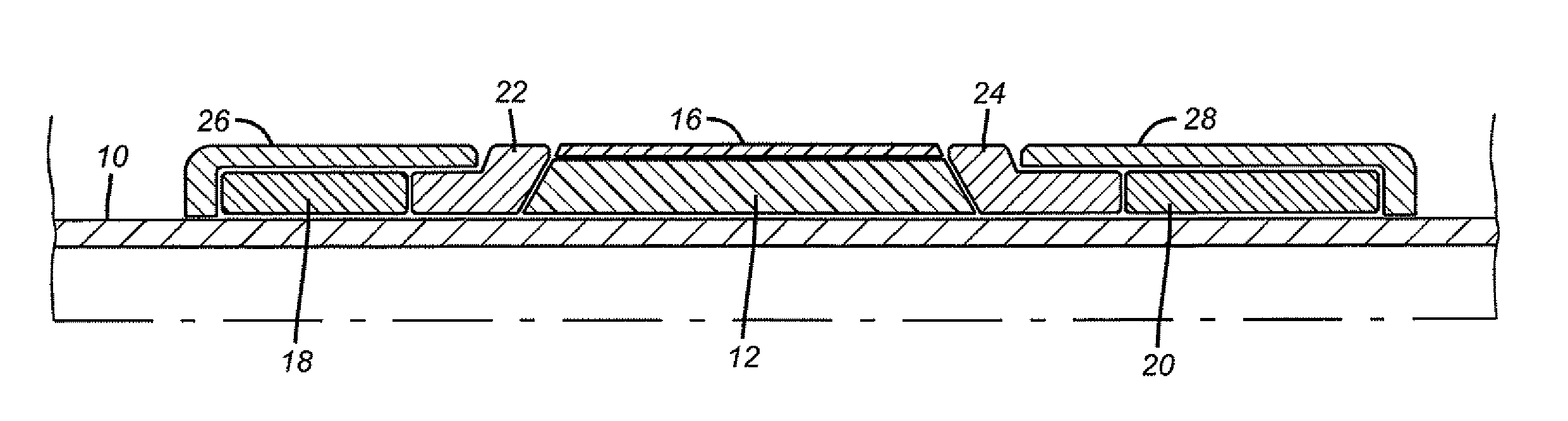
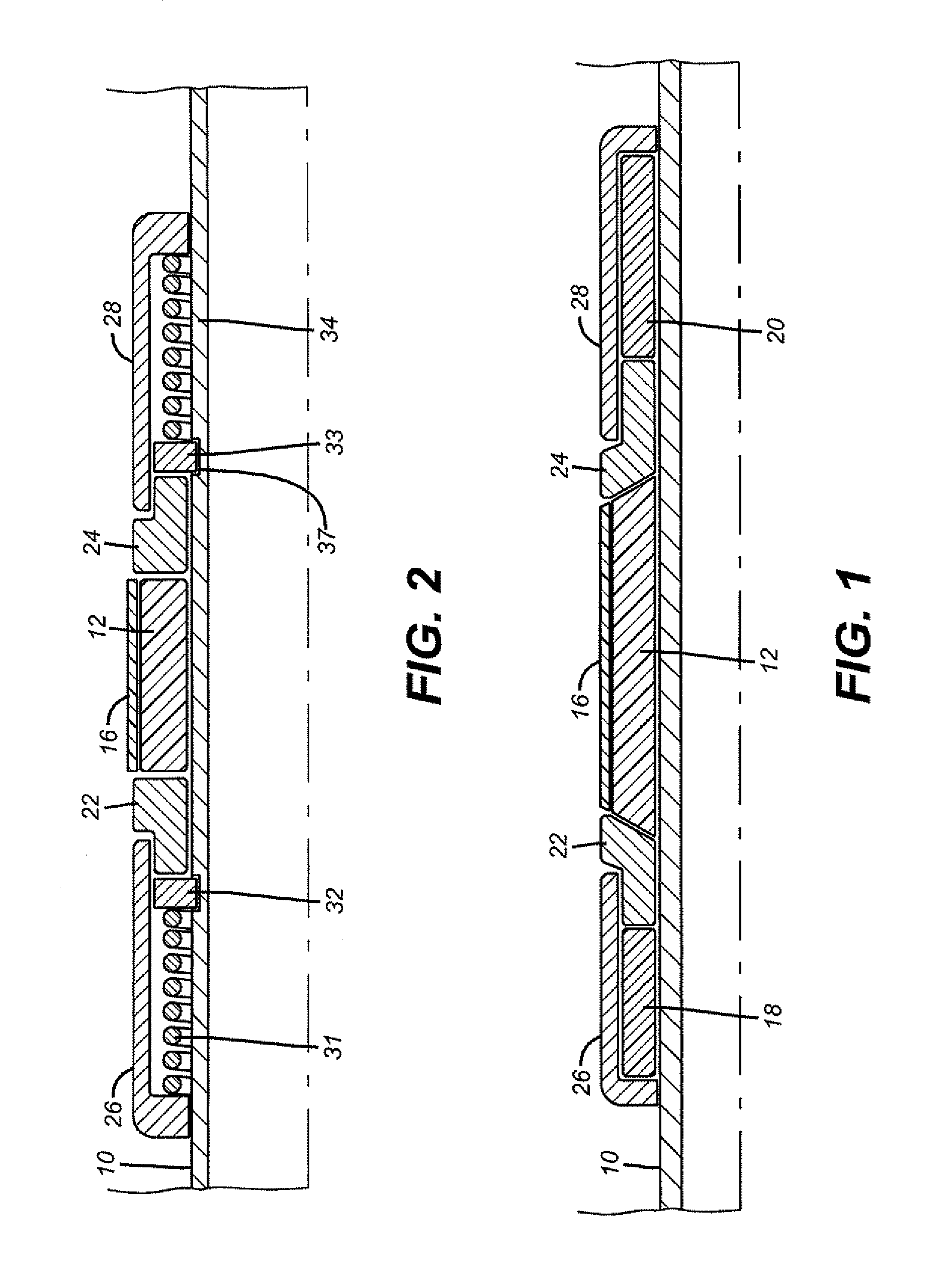
[0059]FIG. 1 shows a mandrel 10 that has a main sealing element 12 mounted to it. The element 12 preferably swells under exposure to well fluids whereupon it grows in radial dimension until it attains contact with the surrounding tubular or the wellbore, neither of which are shown for greater clarity in the drawing. The swelling material can be one of many materials known to swell under exposure to the fluids that are expected to be found at or near the intended setting depth of the packer or plug. A protective sleeve 16 surrounds the main sealing element 12 to not only protect it on the way into the wellbore but also to delay the onset of swelling until the zone of placement is attained. Sleeve 16 can be of a metallic construction or a non-metallic material. Either way the well fluids after a certain duration of exposure will interact with sleeve 16 with the resulting effect that well fluids will then be able to make intimate contact with main sealing element 12 to start it swellin...


PUM


Abstract

A packer or plug features a main sealing element that swells after a delay long enough to get it into proper position. A sleeve eventually goes away to let the well fluids at the main sealing element to start the swelling process until contact with the surrounding tubular or the wellbore is established. Other sleeves that are disposed above and below the main sealing element preferably swell, but mainly in a longitudinal direction against the main sealing element to increase its contact pressure against the surrounding tubular or the wellbore. The longitudinally swelling members may also be covered to initiate their growth after the main sealing element has started or even completed its swelling action. The longitudinally swelling members can be constrained against radial growth to direct most or all of their swelling action longitudinally. Extrusion barriers above and below the main sealing element can optionally be used.

Description

FIELD OF THE INVENTION[0001]The field of his invention is packers and plugs used downhole and more particularly where the packer assembly produces an incremental force to the action that results in placing the element in a sealing position.BACKGROUND OF THE INVENTION[0002]Packers and plugs are used downhole to isolate zones and to seal off part of or entire wells. There are many styles of packers on the market. Some are inflatable and others are mechanically set with a setting tool that creates relative movement to compress a sealing element into contact with a surrounding tubular. Generally, the length of such elements is reduced as the diameter is increased. Pressure is continued from the setting tool so as to build in a pressure into the sealing element when it is in contact with the surrounding tubular.[0003]More recently, packers have been used that employ elements that respond to the surrounding well fluids and swell to form a seal. Many different materials have been disclosed...

Claims


Application Information

Patent Timeline
Patent Type & Authority Patents(United States)
IPC IPC(8): E21B33/12
CPCE21B33/1208E21B33/1216
Inventor MURRAY, DOUGLAS J.ROSENBLATT, STEVE
Owner BAKER HUGHES INC
Why Eureka
Try Eureka