
Synthetic resin clip and hanger with synthetic resin clips

a synthetic resin and clip technology, applied in the direction of snap fasteners, hose connections, scarves, etc., can solve the problems of increasing the number of die parts, and safety issues, and achieves high degree of safety, and high degree of safety

Active Publication Date: 2008-06-17
MISUMI HIDEO
View PDF14 Cites 13 Cited by
  • Summary
  • Abstract
  • Description
  • Claims
  • Application Information

AI Technical Summary

Benefits of technology

"The present invention provides a synthetic resin clip with fly-apart preventing bars that securely receive and prevent the flying apart of broken pieces when the clip's spring breaks. This ensures high safety and reduces the risk of injury or damage. The clip is also easy to assemble and mold, reducing production costs. A hanger with the synthetic resin clip is also provided, which allows for quick and easy assembly."

Problems solved by technology

However, with this synthetic resin clip fitted with the synthetic resin spring made of a composite material having high-density carbonate resin as the main component, the synthetic resin spring breaks at the folded-back portion occasionally upon repeated use of the clip, and since pieces of the broken synthetic resin spring that fly apart may injure a hand, face, etc., there was an issue in terms of safety.
Though the covering of the synthetic resin spring in the process of molding the clip members may be considered, this may disable the release from a molding die or make the molding die become complicated in structure or increase the number of dies (number of die parts) etc., and thereby increase the initial cost or the running cost.
There was thus the possibility that safety could not be secured adequately.

Method used


Image

  • Synthetic resin clip and hanger with synthetic resin clips
  • Synthetic resin clip and hanger with synthetic resin clips
  • Synthetic resin clip and hanger with synthetic resin clips

Examples


embodiment 1

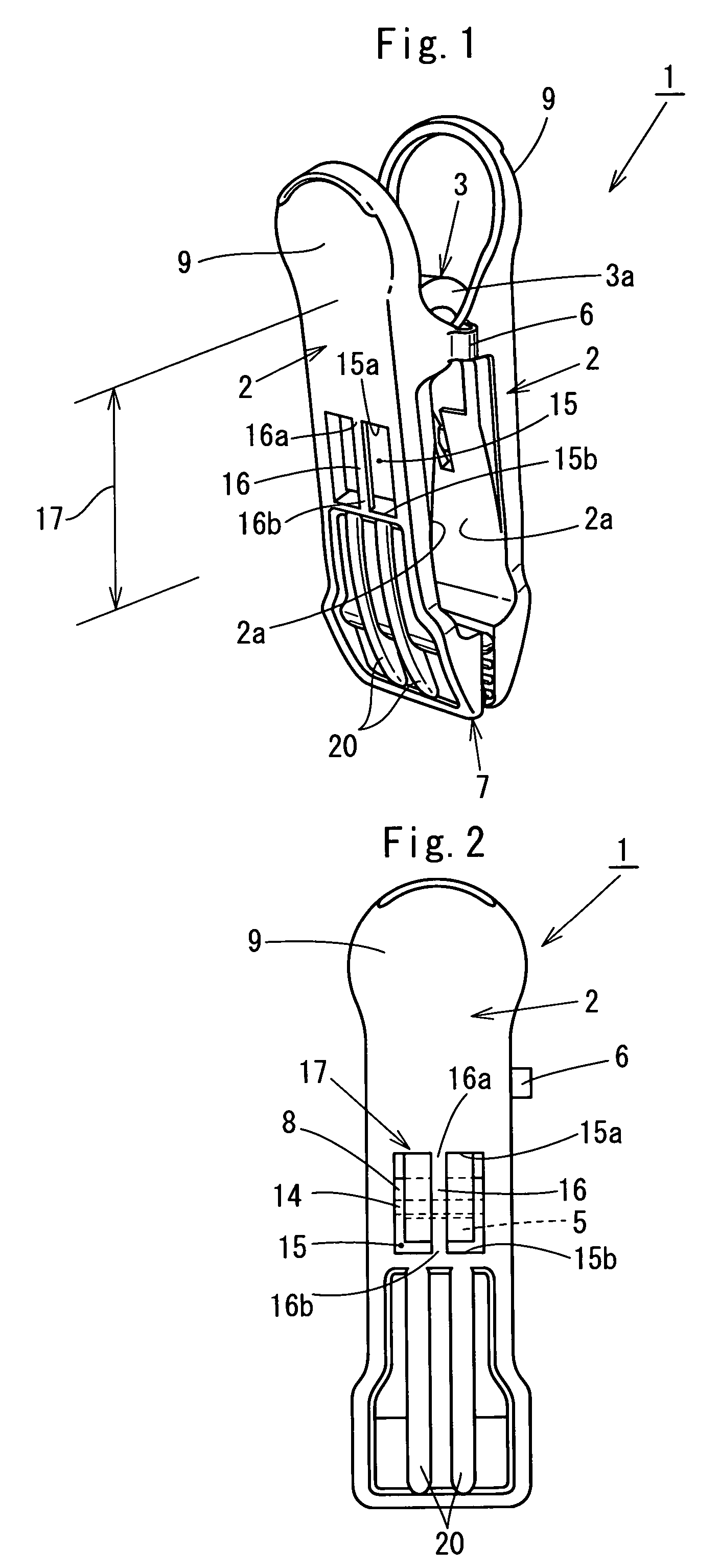
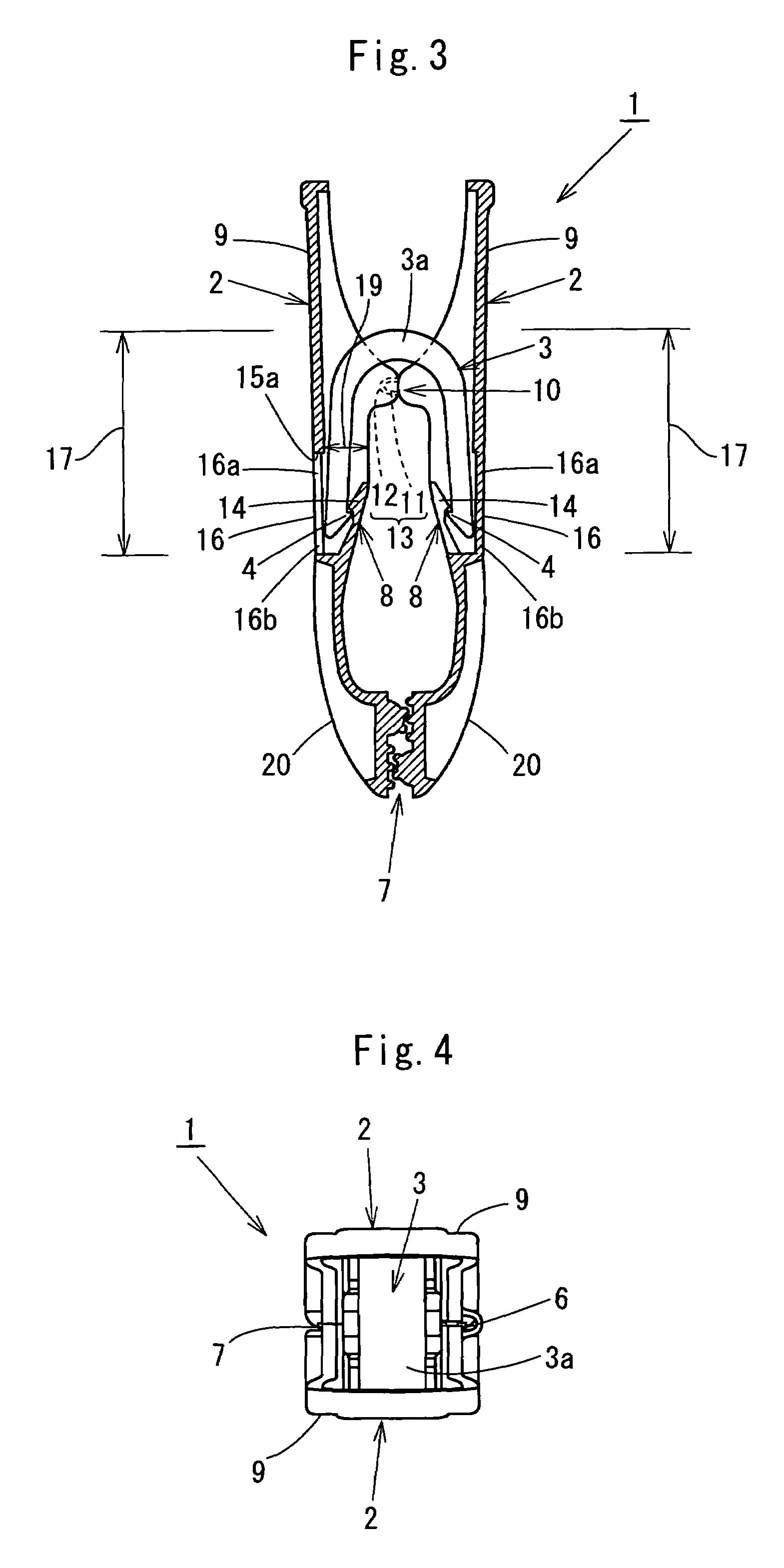
[0030]FIG. 1 is a perspective view of a synthetic resin clip, FIG. 2 is a front view of the synthetic resin clip, FIG. 3 is a longitudinal sectional view of the synthetic resin clip, FIG. 4 is a plan view of the synthetic resin clip, FIG. 5 is a right side view of the synthetic resin clip, FIG. 6 is a left side view of the synthetic resin clip, and FIG. 7 is an exploded view of the synthetic resin clip prior to assembly, and in the figures, symbol 1 indicates the synthetic resin clip in its entirety.

[0031]This synthetic resin clip 1 is arranged by making a pair of clip members 2, formed of synthetic resin and to be of substantially the same shape, oppose each other face-to-face and by fitting a synthetic resin spring 3 across clip members 2.

[0032]As shown in FIGS. 3 and 7, synthetic resin spring 3 is formed of a composite material synthetic resin having high-density carbonate resin as the main component, and is formed to have an inverted “U” shape that is thick at a folded-back port...

embodiment 2

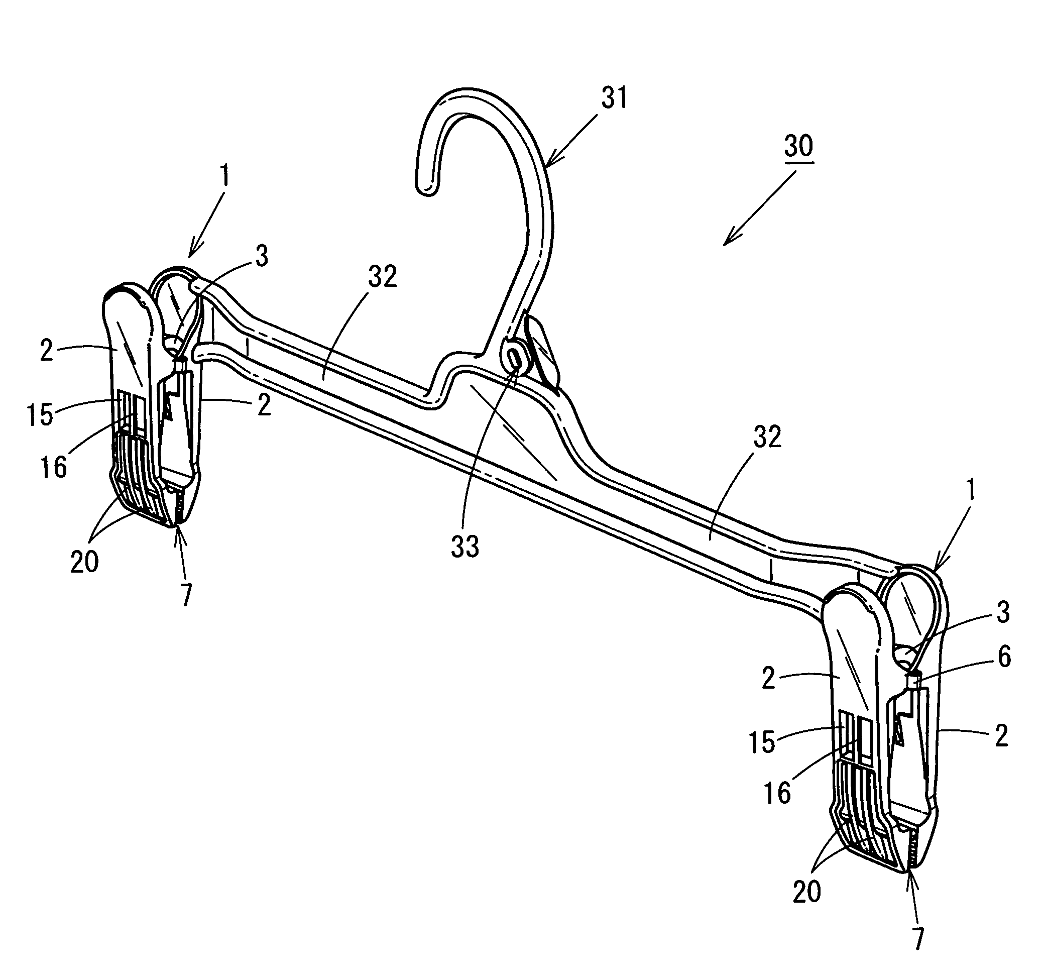
[0053]As shown in FIGS. 8 to 11, this embodiment is a hanger 30, equipped with synthetic resin clips 1 of the above-described embodiment.

[0054]With this hanger 30, equipped with synthetic resin clips 1, one clip member 2, of the pair of clip members 2 connected by thin portion 6 as described with Embodiment 1, is integrally formed at each of both tip portions (left and right tip portions in FIG. 9) of an arm 32, with the arm 32 having a hanging hook 31 formed at a central portion.

[0055]That is as described above, in synthetic resin clip 1, engaging portions 5 are formed on inner surface portions of the tips of synthetic resin spring 3, which is formed in a “U” shape by being folded back at an intermediate portion. Window holes 15 for sliding of molding dies are formed on outer portions of clip members 2 in order to form receiving portions 8, which engage with engaging portions 5, at inner portions of clip members 2. Insertion spaces 19, into which the tip portions of synthetic resin...


PUM


Abstract

In order to provide a synthetic resin clip and a hanger with synthetic resin clips that are high in safety and can yet be produced at low cost, a synthetic resin clip and synthetic resin clips to be provided on a hanger are arranged with engaging portions being formed on inner surface portions of tips of a synthetic resin spring, which is formed in a “U” shape by being folded back at an intermediate portion, window holes for sliding of molding dies being formed on outer portions of clip members in order to form receiving portions, engaging with the engaging portions, at inner portions of the clip members, insertion spaces, into which the tip portions of the synthetic resin spring are inserted, being formed in the direction of sliding of the dies between upper edges of the window holes and upper end portions of the receiving portions, and fly-apart preventing bars being disposed across the upper and lower edges of the window holes.

Description

BACKGROUND OF THE INVENTION[0001]1. Field of the Invention[0002]This invention relates to a synthetic resin clip and a hanger with synthetic resin clips.[0003]2. Description of the Related Art[0004]In general, clothes, etc., are delivered in the state of being hung on an above-mentioned hanger when being delivered from a manufacturer of the clothes, etc., to a trading firm or from a trading firm to a retail shop, and recently, in accordance with product liability laws, that is, so-called “PL laws,” deliveries are made upon confirming by a metal detector that needles, etc., are not remaining in the clothes and other sewn products. With a synthetic resin clip, with which clamping portions of clip members are elastically urged in the direction of pressing against each other by a “U” shaped metal spring, the metal detector responds to the metal spring.[0005]In order to accommodate for such a metal detector, an arrangement is used wherein a synthetic resin spring, which has elasticity, i...

Claims


Application Information

Patent Timeline
Patent Type & Authority Patents(United States)
IPC IPC(8): A41D27/22
CPCA47G25/485D06F55/02Y10T24/3439Y10T24/3428Y10T24/3427Y10T24/3443Y10T24/13
Inventor MISUMI, HIDEO
Owner MISUMI HIDEO
Learn More