Methods for producing low-visibility retroreflective visual tags

a retroreflective, low-visibility technology, applied in the direction of instruments, sensing record carriers, sensing by electromagnetic radiation, etc., can solve the problems of inability to pinpoint the exact location of objects, short range operation of rfid tag readers, and poor function of existing unpowered passive rfid tag readers

Active Publication Date: 2008-06-17
XEROX CORP
View PDF9 Cites 86 Cited by
  • Summary
  • Abstract
  • Description
  • Claims
  • Application Information

AI Technical Summary

Benefits of technology

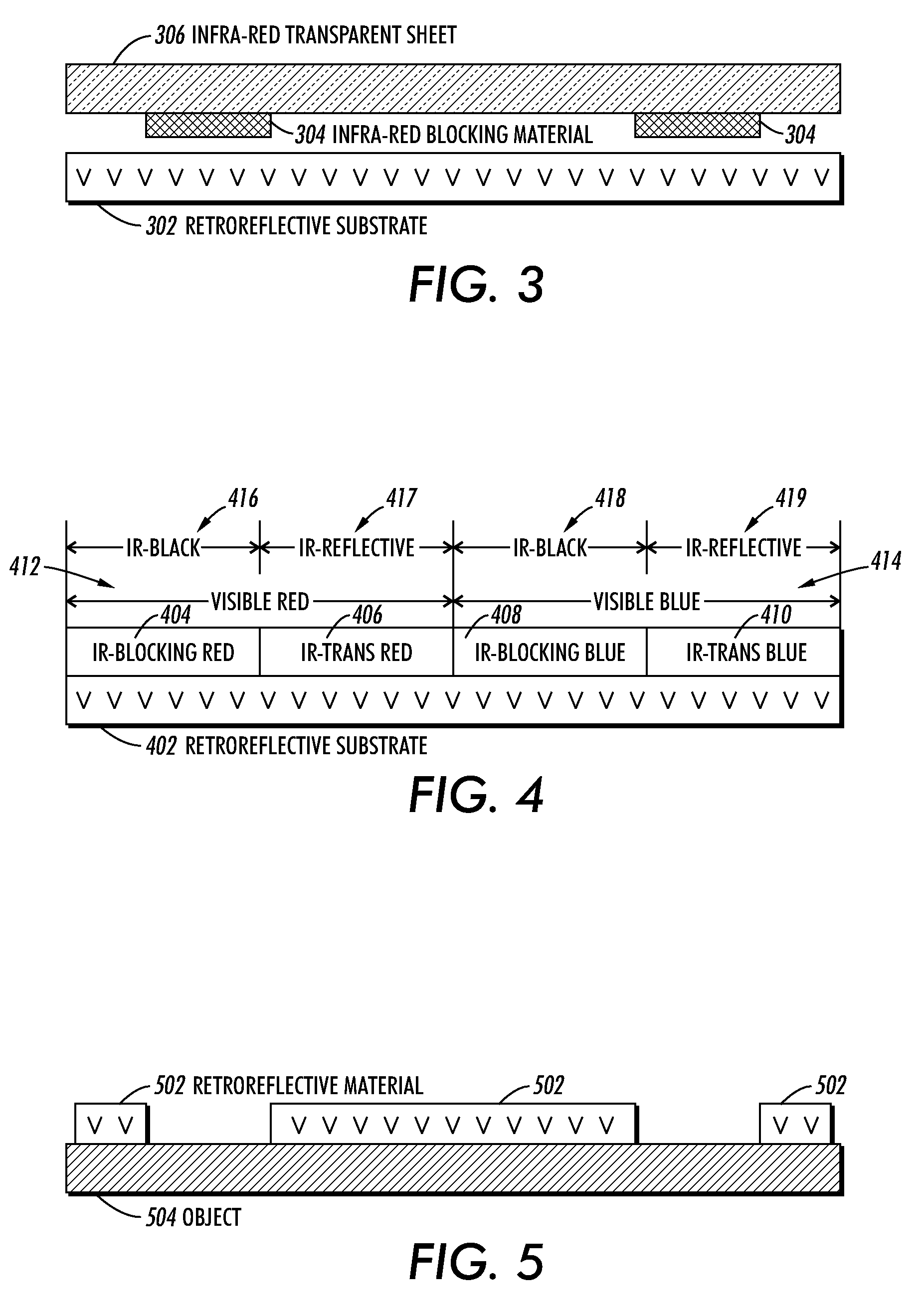
[0015]In a variation on this embodiment, in addition to the infra-red-blocking material which is placed over the retroreflective substrate, the process places an infra-red-transparent material over the low-visibility retroreflective visual tag. This infra-red-transparent material has one or more visible colors, which form a standardized visible pattern which makes it easier to identify a low-visibility retroreflective visual tag.
[0016]In a variation on this embodiment, the retroreflective substrate is in the form of a pre-printed sheet or label, which is the size of a standard-sized sheet of paper. This sheet can be pre-printed with an “invisible” IR-reflective pattern. This allows a visible pattern to be printed on the sheet using an infra-red-transparent material or in non-marked parts of the sheet, thereby allowing users to print their content onto sheets which are pre-printed with tags which are only visible using an IR illuminator and camera.
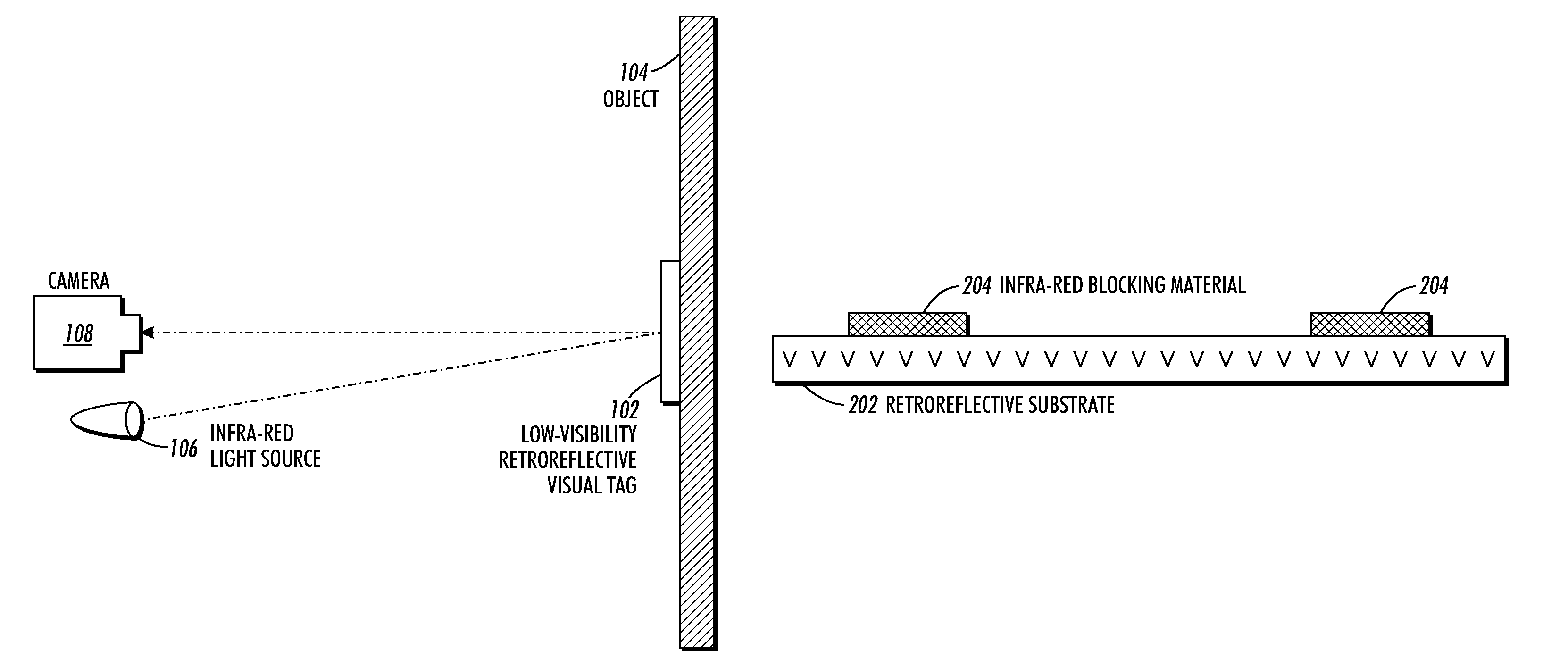
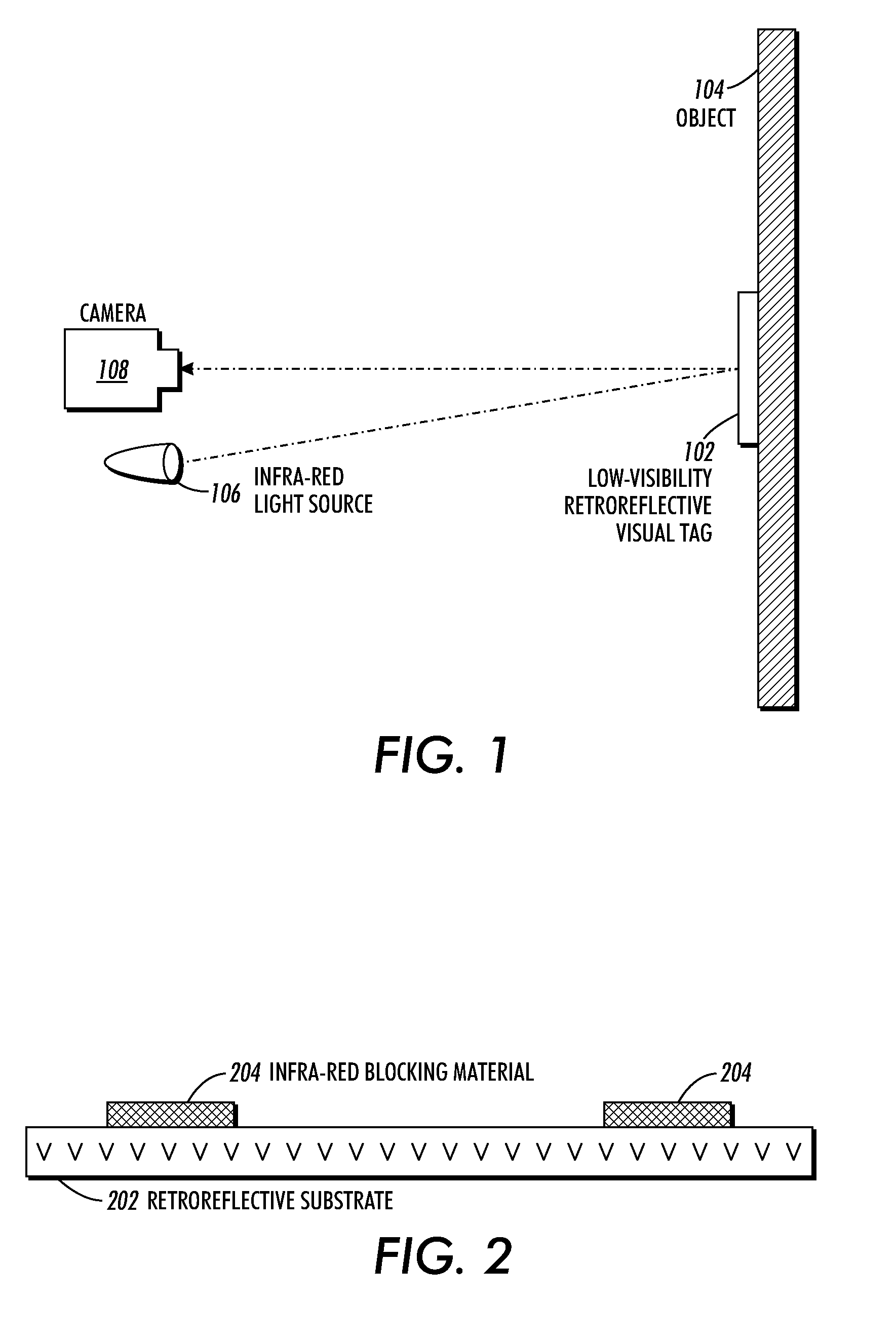
[0019]One embodiment of the present invention provides a process for producing a low-visibility retroreflective visual tag. This process operates by depositing a retroreflective material onto a desired object to form the low-visibility retroreflective visual tag. This retroreflective material is deposited so as to form a pattern which becomes visible to an infrared sensor when the low-visibility retroreflective visual tag is illuminated by an infra-red light source. Furthermore, this retroreflective material is substantially transparent to visible light. Consequently, the pattern formed by the retroreflective material is less visible under visible light, and an underlying visible pattern on the desired object is visible through the retroreflective material.

Problems solved by technology

However, existing unpowered “passive” RFID tag readers cannot pinpoint the exact location of an object.
Moreover, RFID tag readers only operate at short range.
They also function badly in the presence of metal, and interfere with each other when many tagged objects are present.
However, these techniques require expensive, power-consuming electronics and batteries, and they still may not determine position accurately when attached to dense or metallic objects.
Visual tag-based methods do not have the same problems, but the task of recognizing visual tags is itself a complicated problem, which requires a large amount of computation.
Consequently, existing systems have difficulty distinguishing tags from complex backgrounds or handling variable lighting.
They also require too much computational power to be practical in many applications.
Moreover, large, visually-prominent tags, which are easier to recognize, are not aesthetically pleasing, and are consequently unsuitable for many applications.

Method used


Image

  • Methods for producing low-visibility retroreflective visual tags
  • Methods for producing low-visibility retroreflective visual tags
  • Methods for producing low-visibility retroreflective visual tags

Examples


Embodiment Construction

[0030]The following description is presented to enable any person skilled in the art to make and use the invention, and is provided in the context of a particular application and its requirements. Various modifications to the disclosed embodiments will be readily apparent to those skilled in the art, and the general principles defined herein may be applied to other embodiments and applications without departing from the spirit and scope of the present invention. Thus, the present invention is not limited to the embodiments shown, but is to be accorded the widest scope consistent with the principles and features disclosed herein.

[0031]The data structures and code described in this detailed description are typically stored on a computer-readable storage medium, which may be any device or medium that can store code and / or data for use by a computer system. This includes, but is not limited to, magnetic and optical storage devices such as disk drives, magnetic tape, CDs (compact discs) ...


PUM


Abstract

A process for producing a low-visibility retroreflective visual tag, which can be used to identify and / or determine the position of an object. This process involves placing an infra-red-blocking material over a retroreflective substrate to form the low-visibility retroreflective visual tag. This infra-red-blocking material is placed so as to form a pattern, which becomes visible to an infrared sensor when the low-visibility retroreflective visual tag is illuminated by an infra-red light source.

Description

BACKGROUND[0001]1. Field of the Invention[0002]The present invention relates to techniques for manufacturing visual tags or makers. More specifically, the present invention relates to techniques for producing low-visibility retroreflective visual tags.[0003]2. Related Art[0004]A relatively inexpensive technique for identifying an object and for determining the position of an object in the physical world is to attach a Radio Frequency Identification (RFID) tag to the object. RFID tags are relatively small and inexpensive, and generally do not require a power source. Because of these advantages, RFID tags (although mostly of the battery-powered “active” variety) are widely used in numerous applications as diverse as inventory-control systems, and electronic toll booths on freeways.[0005]However, existing unpowered “passive” RFID tag readers cannot pinpoint the exact location of an object. Rather, they simply report the presence or absence of a tag in their field of sensitivity. Moreov...

Claims


Application Information

Patent Timeline
Patent Type & Authority Patents(United States)
IPC IPC(8): G02B5/122G06K7/10
CPCG06K19/06046G06K2019/06225
Inventor REICH, JAMES E.CHEUNG, PATRICK C. P.SHRADER, ERIC J.HUANG, QINGFENG
Owner XEROX CORP
Why Eureka
Try Eureka