
Equipment and method for changing a blade in a coating device

a coating device and blade technology, applied in the direction of coatings, pretreated surfaces, applied substance rearrangement, etc., can solve the problems of losing the properties required for a successful coating, affecting the effect of coating quality, so as to achieve simple and reliable construction.

Inactive Publication Date: 2008-06-17
VALMET TECH INC
View PDF12 Cites 0 Cited by
  • Summary
  • Abstract
  • Description
  • Claims
  • Application Information

AI Technical Summary

Benefits of technology

"The present invention is about creating equipment and a method for changing blades in a coating device. The equipment is simple and easy to operate, and can even change blades automatically. The use of the equipment solves problems caused by the structure of the coating device. The method involves shaping the blade and using a blade band, which can be easily brought to the blade holder and set in place quickly. The use of the method allows for faster blade changes, without interruptions in the coating process and without requiring any additional work by the machine operation personnel. The invention also includes the use of jointing devices to smoothly change blade-band reels. Overall, the invention provides a solution for coating devices to improve blade changing efficiency."

Problems solved by technology

In coating, the blade wears in a very short time, causing it to lose the properties required for a successful coating result.
However, it is difficult and even dangerous to change long blades.
In addition, the regular changing of blades takes up a great deal of useful production time, leading to production losses.
Further, during blade changing, uncoated broke is created, especially in situations in which coating takes place as an on-line operation in connection with the paper machine.
Besides reducing effective production time, blade changes also tie up labor.
However, in known types of coating devices, structural factors make the equipment described above unsuitable for changing coating blades.
Due to this, among other factors, known types of blade-changing equipment are in no way suitable for use in coating devices.
In addition, it would also be difficult to feed the band using known types of equipment, as in reality there is generally little installation space in connection with coating devices.

Method used


Image

  • Equipment and method for changing a blade in a coating device
  • Equipment and method for changing a blade in a coating device
  • Equipment and method for changing a blade in a coating device

Examples


Embodiment Construction

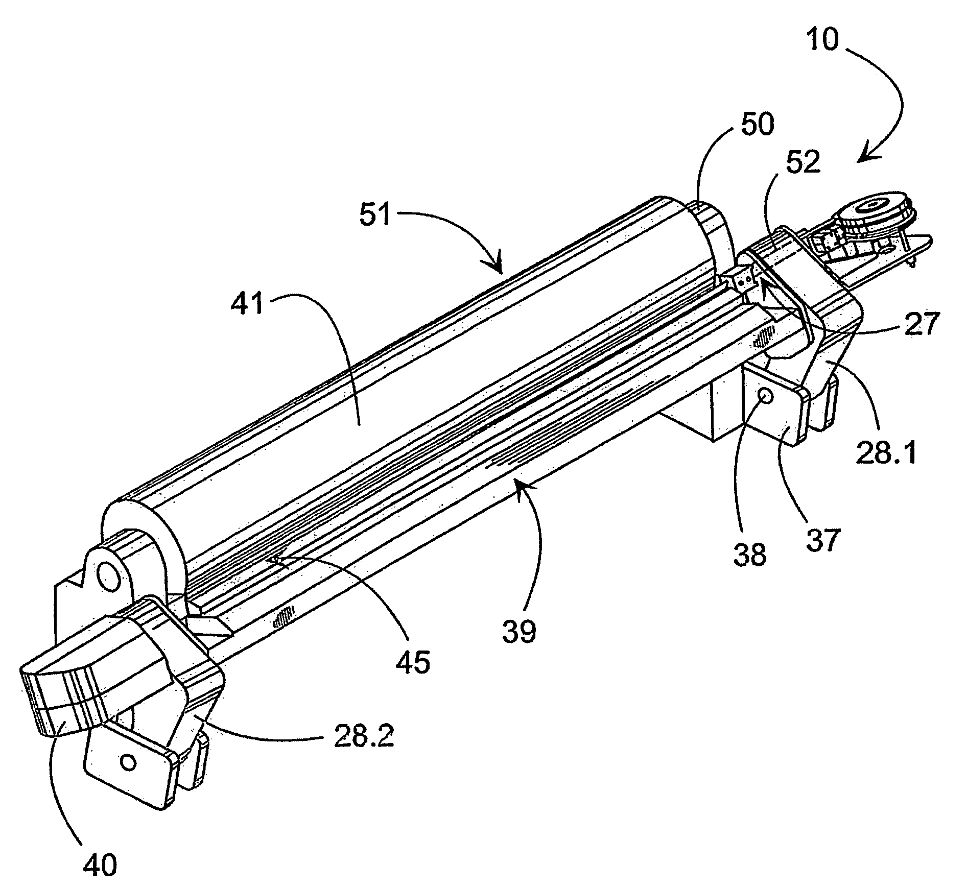
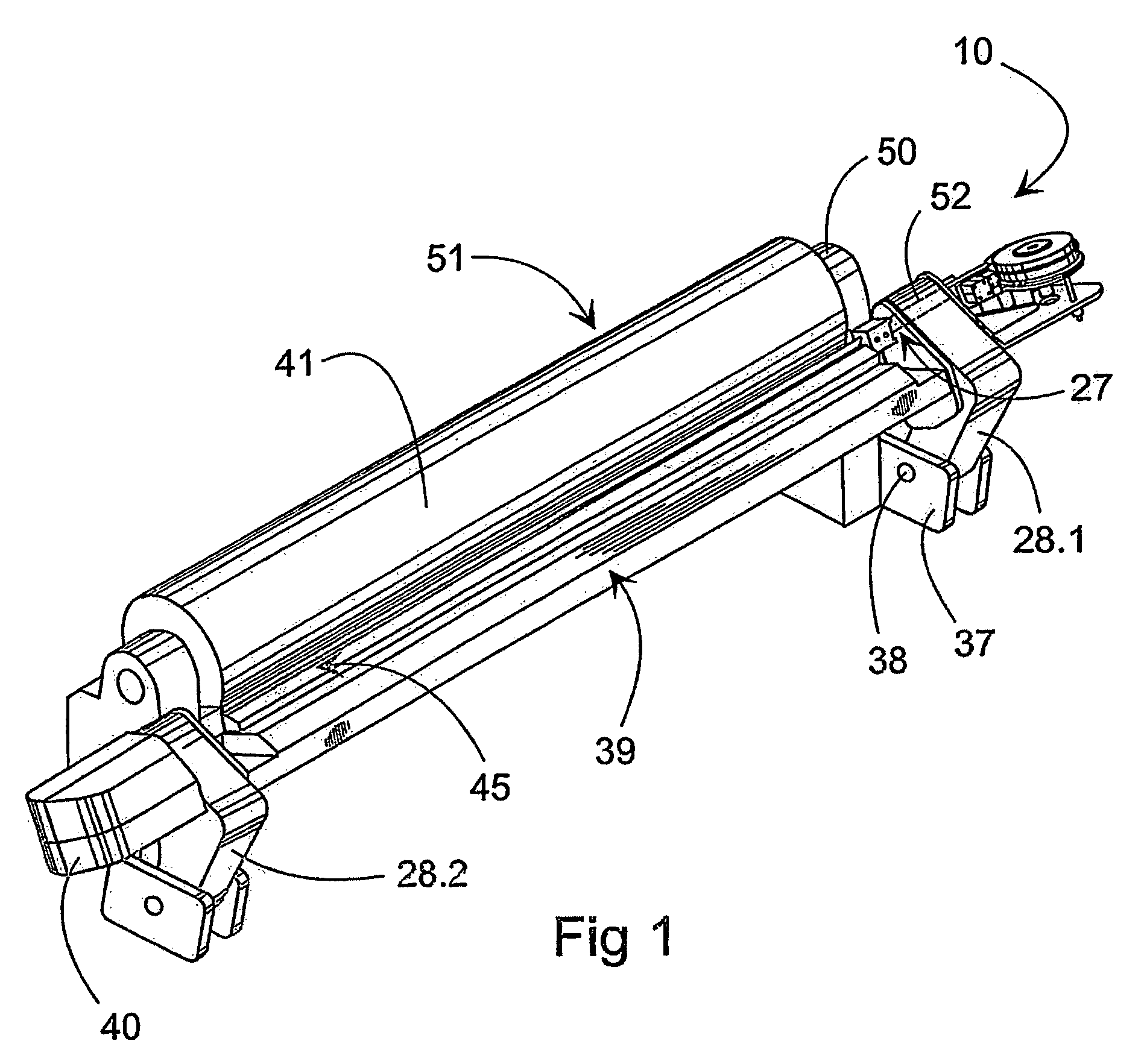
[0026]FIG. 1 shows a rough diagram of the coating device 51 and the location of the equipment 10, 40 according to the invention, in connection with it. It should be noted that FIG. 1 shows only those parts of the coating device 51 that are essential from the point of view of the invention. The coating device 51 shown is used to perform so-called blade coating, for carrying out which there are several different ways according to the prior art. Examples of these are brushing-roll, short-delay, and nozzle-applications, the implementations of which are not discussed in greater detail in this connection.

[0027]Using the coating device 51 of the type shown, the paper web 42.1, 42.2 (FIGS. 5a, 5b) is brought onto the surface of the backing roll 41. The paper web 42.1 is brought to the backing roll 41, which is supported on a fixed frame 50, from the side of the roll 41 opposite to the blade holder 45. Depending on the type of application, the coating is applied to the surface of the web 42....


PUM

PropertyMeasurementUnit
running timeaaaaaaaaaa
flexibleaaaaaaaaaa
lengthaaaaaaaaaa

Abstract

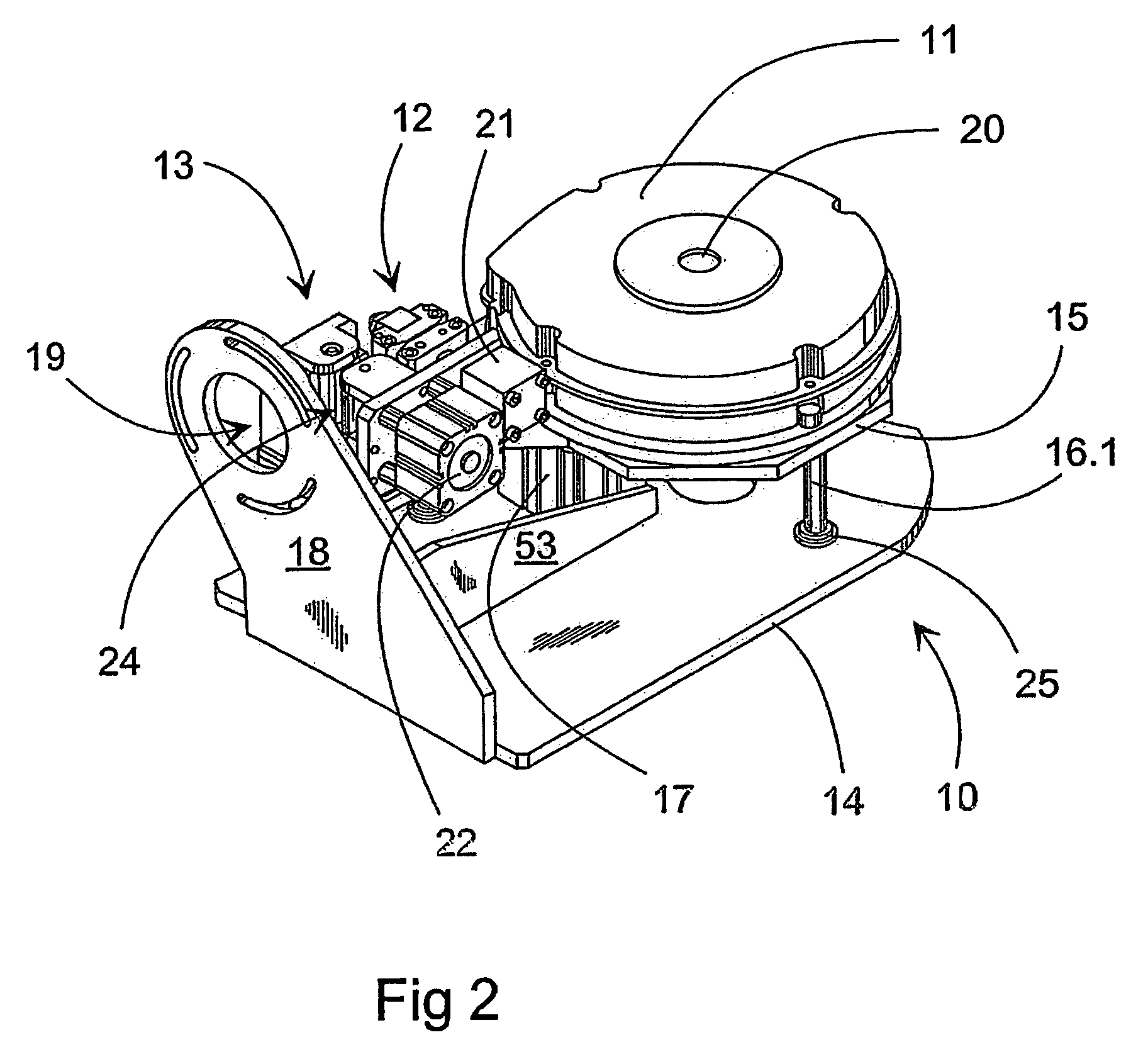
Equipment for changing a blade (43) in a coating device (51) changes several blades (43) arranged in a band (43). The equipment includes reels (11, 40) connected to the ends of the blade holder (45), for holding the reeled unused and used band (43); transfer devices (13, 20) for moving the band (43) in connection with the blade holder (45), and lifting devices (17) for lifting the band (43) up and lowering it into the blade holder (45). Indentations (44) at least the length of the hollow shaft (52) are arranged at regular intervals on the band (43), and are arranged to permit the blade (43) to be lowered into the blade holder (45).

Description

CROSS REFERENCES TO RELATED APPLICATIONS[0001]This application is a U.S. national stage application of international app. No. PCT / FI2004 / 050018, filed Feb. 19, 2004, the disclosure of which is incorporated by reference herein, and claims priority on Finnish Application No. 20035024, filed Feb. 27, 2003.STATEMENT AS TO RIGHTS TO INVENTIONS MADE UNDER FEDERALLY SPONSORED RESEARCH AND DEVELOPMENT[0002]Not applicable.BACKGROUND OF THE INVENTION[0003]The present invention relates to equipment for changing a blade in a coating device, in which the blade is intended to be used in connection with coating, in a blade holder fitted to a blade beam, and in which the blade is formed as an elongated flexible band, the coating device including[0004]a blade-beam suspension arranged in connection with the frame at the ends of the blade beam, and which is arranged in a hollow shaft fitted to the frame, in such a way that, in the running position, the central axis of the hollow shaft is arranged to l...

Claims


Application Information

Patent Timeline
Patent Type & Authority Patents(United States)
IPC IPC(8): B05D1/40B05C1/14B05C11/02B05C11/04D21H25/10
CPCB05C11/026B05C11/041B05C11/045D21H25/10B05C11/044B05C11/04Y10T29/49766Y10T29/5198
Inventor NIKKANEN, VILLEPARVIAINEN, SEPPOVAANOLA, MARKKU
Owner VALMET TECH INC
Learn More