Window aerial for motor vehicles

a technology for automobile windows and windows, applied in the direction of antennas, antenna supports/mountings, coatings, etc., can solve the problems of not always obtaining desired transmission power, inability to provide said coupling electrodes, and inability to fully achieve the establishment of electrical contact of the whole set of wires with the common connection electrode (at the base of the antenna)

Active Publication Date: 2008-06-17
SAINT-GOBAIN GLASS FRANCE
View PDF6 Cites 7 Cited by
  • Summary
  • Abstract
  • Description
  • Claims
  • Application Information

AI Technical Summary

Benefits of technology

[0016]With all these measures, the rate of scrap accumulating due to failures of contact in the coupling electrode of finished glazings is appreciably reduced as compared with the known antenna glazing, and after fitting of such a glazing into an automobile, a checking function is still possible.
[0017]The number of wires overlaid on the antenna in the form of a thin layer and hence the transmission power of the capacitor thus formed may be influenced depending on requirements by the laying of several loops inside a coupling electrode or simply by a simple or multiple fold of a loop taking a sinuous profile. The latter measure makes it possible to obtain a large surface coverage, without, however, losing the possibility of performing a simple check of continuity. As the case may be, it would be possible to form a single electrode according to the invention from several wires of the type described hereinabove.
[0019]Within the framework of a fitting for diversity at the antenna, provision may be made, in an antenna glazing, for several coupling electrodes constructed in accordance with the invention, distributed around the rim of the glazing. In an advantageous manner, the connections of ends of several coupling electrodes (for example in the corners) may be joined on the edge of the glazing, in local proximity to one another, and contacted towards the outside with several poles, possibly with a common interface. This may simplify the manner of proceeding in the logistic circuit and also the fitting of the electrical connections of such a glazing.

Problems solved by technology

It is therefore not possible to provide said coupling electrode very near to the edge of said glazing where it might be optically hidden by the framework of the window.
Practical applications of the thin wires coupling electrode show, however, that with the wires connected at one end only, the desired transmission power is not always obtained.
Within the framework of industrial manufacture, the establishment of electrical contact of the whole set of wires with the common connection electrode (at the base of the antenna) may not, however, be fully achieved.
In the final analysis, there is no reliable test procedure making it possible to test the operating capacitance of the coupling electrode before and / or after the manufacture of the composite forming the glazing.
If manufacture has terminated, and if defective coupling is found thereafter, the whole pane has to be scrapped.
It would however still always be necessary to test each wire individually or its contact with the base of the antenna, so much so that a noticeable reduction in expenditure cannot be expected from this variant.

Method used


Image

  • Window aerial for motor vehicles
  • Window aerial for motor vehicles
  • Window aerial for motor vehicles

Examples


Embodiment Construction

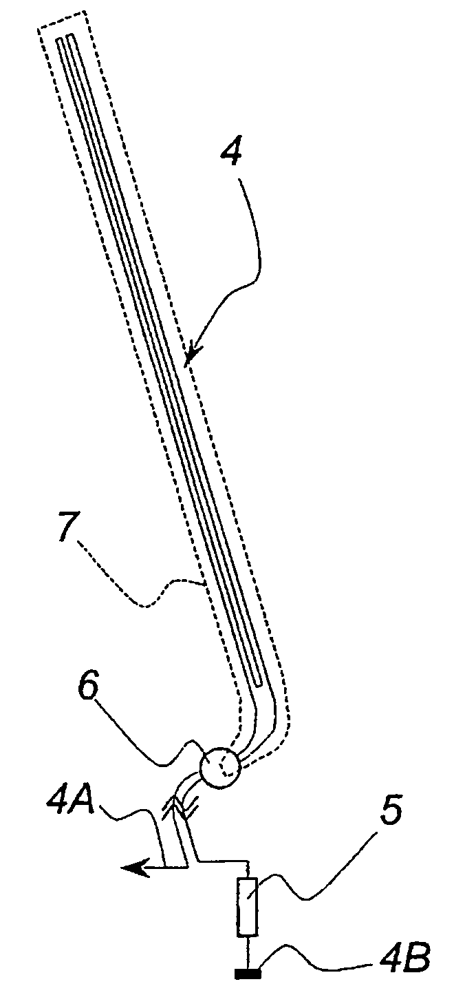
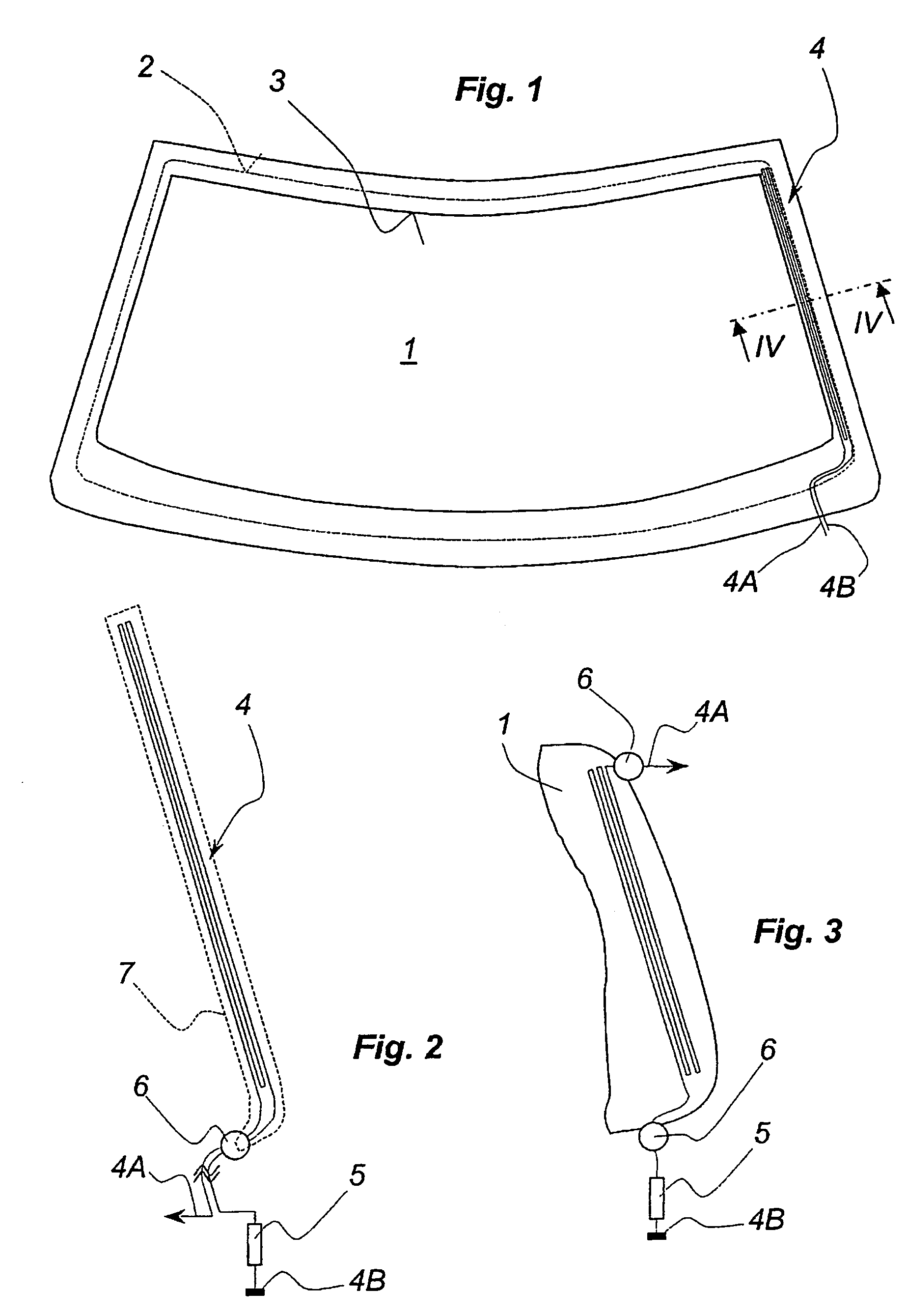
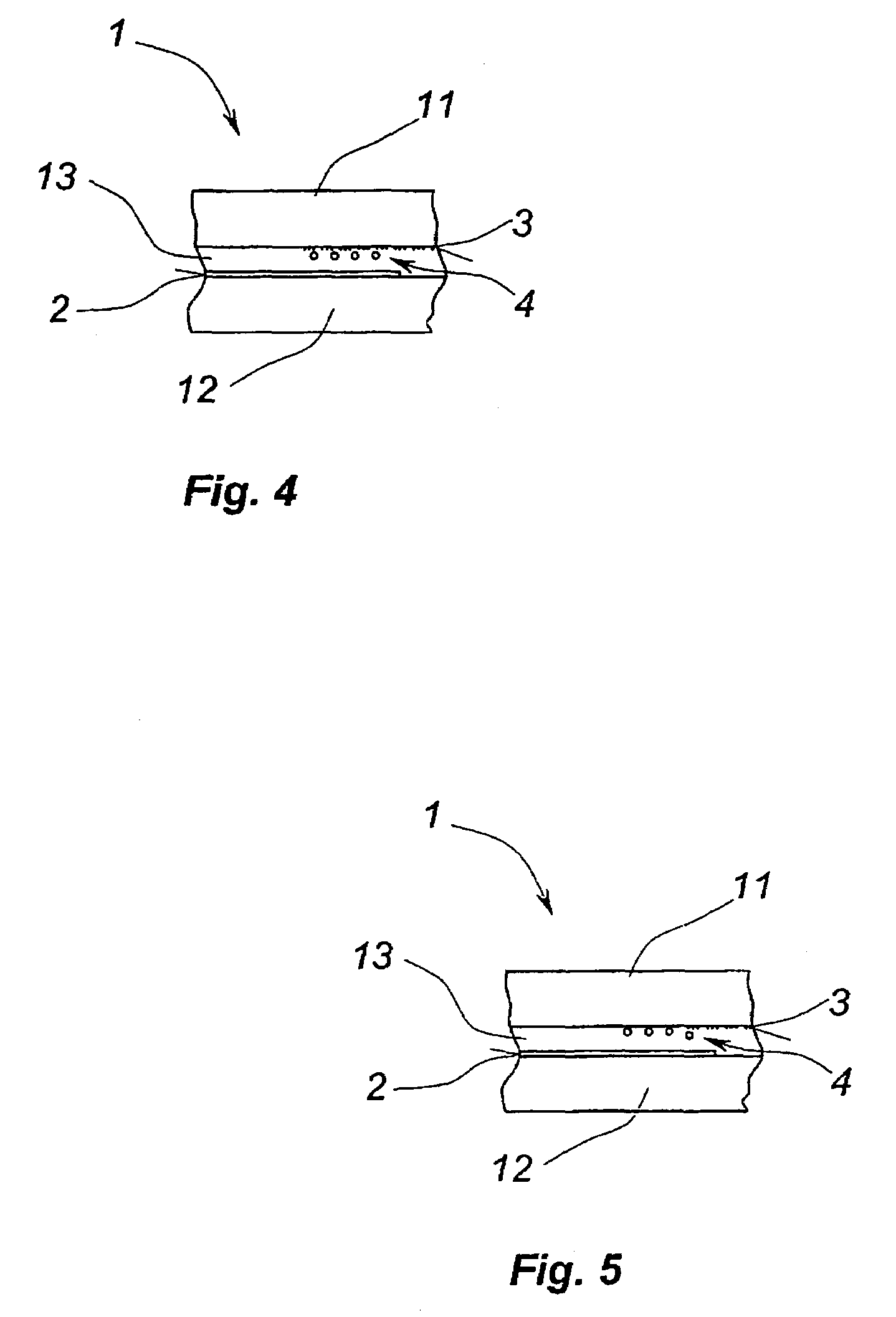
[0030]According to FIG. 1, an antenna glazing 1 is furnished with an electrically conducting cladding 2 over the whole of its surface, but which has nevertheless been parted away from the rim in the zone at the edge of the glazing 1 or has not been applied at all. A dashed line demarcates the outside edge of the cladding homogeneously covering the visual field of the glazing 1. At the periphery, over the whole of the outer rim of the glazing 1, an opaque edge strip 3, known per se, has also been provided, surrounding the visual field proper of the glazing 1. This edge strip 3 is in practice composed of an opaque ink, for example a curable screen-printing paste, and overlaps or covers on the one hand the customary adhesion-based fixation of such a glazing, and on the other hand, also the edge of the cladding 2. Here, it has however been drawn see-through for representational requirements.

[0031]As already stated, such an antenna glazing 1 is glued to a collar, generally metallic, of a...


PUM

PropertyMeasurementUnit
diameteraaaaaaaaaa
diameteraaaaaaaaaa
diameteraaaaaaaaaa

Abstract

An antenna glazing for automobiles, including an electrically conducting cladding extending surface-wise over the surface of the glazing up to a zone of the free edge of the cladding, serving as an antenna element, and a coupling electrode furnished with external connections, coupled in the capacitive regime to the electrically conducting cladding with interposition of an insulating layer. The coupling electrode is composed at least of one thin wire, which starts from the zone at the edge of the glazing, is conducted over the surface covered by the cladding, and is returned to the zone of the edge with at least one fold, so that the two ends of the wire are situated in the zone of the edge of the glazing.

Description

FIELD OF THE INVENTION[0001]The invention relates to an antenna glazing for automobiles exhibiting the characteristics of the preamble of claim 1.DISCUSSION OF THE BACKGROUND[0002]Document DE 198 32 228 C2 discloses an antenna glazing for automobiles possessing these characteristics, in which an electrically conducting cladding is used as antenna element. To decouple antenna signals originating from the cladding placed inside the glazing made in the guise of composite glazing, a coupling electrode is coupled in the capacitive regime to said cladding. Said electrode is composed of a plurality of thin wires placed parallel to and some distance from one another, which are linked electrically at one end by means of a busbar or similar, and extend over the cladding starting from this connection. The dielectric intermediate layer of the capacitor thus formed is constituted by at least one adhesive layer of the composite.[0003]This form of construction of a coupling electrode offers, by co...

Claims


Application Information

Patent Timeline
Patent Type & Authority Patents(United States)
IPC IPC(8): H01Q1/32B32B17/10H01Q1/12H01Q21/28
CPCB32B17/10036B32B17/10376B32B17/10761H01Q1/1285H01Q21/28B32B17/10174H01Q1/32
Inventor MAEUSER, HELMUT
Owner SAINT-GOBAIN GLASS FRANCE
Why Eureka
Try Eureka