
Integrated circuit design utilizing array of functionally interchangeable dynamic logic cells

a dynamic logic and integrated circuit technology, applied in the field of integrated circuits and integrated circuit design, can solve the problems of inability to design integrated circuits, the complexity of electronic integrated circuits, and the complexity of electronic integrated circuits or “chips” has increased, and the design of integrated circuits has also become more difficul

Active Publication Date: 2008-06-17
MARVELL ASIA PTE LTD
View PDF1 Cites 0 Cited by
  • Summary
  • Abstract
  • Description
  • Claims
  • Application Information

AI Technical Summary

Benefits of technology

[0014]These and other advantages and features, which characterize the invention, are set forth in the claims annexed hereto and forming a further part hereof. However, for a better understanding of the invention, and of the advantages and objectives attained through its use, reference should be made to the Drawings, and to the accompanying descriptive matter, in which there is described exemplary embodiments of the invention.

Problems solved by technology

Electronic integrated circuits, or “chips” have become significantly more complex as circuit fabrication technologies have improved.
The design of integrated circuits has likewise become more difficult as complexity has increased.
Whereas early chips were often designed gate by gate, more advanced integrated circuits incorporating millions of gates represent too much of an undertaking for early design methodologies.
Conventional logic design using logic cells, however, suffers from a number of drawbacks.
Often the logic cells differ in size and shape, which can lead to inefficient space utilization when placed in a design.
Furthermore, routing of the interconnects and clock signals is often haphazard and irregular, in many instances creating timing problems such as skew and jitter that require excessive testing and redesign.
In addition, conventional design methodologies and tools have typically been limited to use with logic cells implemented using static logic.
Logic synthesis tools have conventionally been unable to effectively utilize dynamic logic due in part to tighter stricter timing constraints associated with dynamic logic.
In many cases, automated routing of the clock and interconnect signals is simply too irregular to meet the strict timing requirements of dynamic circuits.
Yet another drawback of conventional design methodologies arises when changes in the logic design a required at later stages of the development cycle.
If such dummy cells are never utilized, however, the space allocated to the dummy cell is effectively wasted, thus increasing the size and overall cost of the design.

Method used


Image

  • Integrated circuit design utilizing array of functionally interchangeable dynamic logic cells
  • Integrated circuit design utilizing array of functionally interchangeable dynamic logic cells
  • Integrated circuit design utilizing array of functionally interchangeable dynamic logic cells

Examples


Embodiment Construction

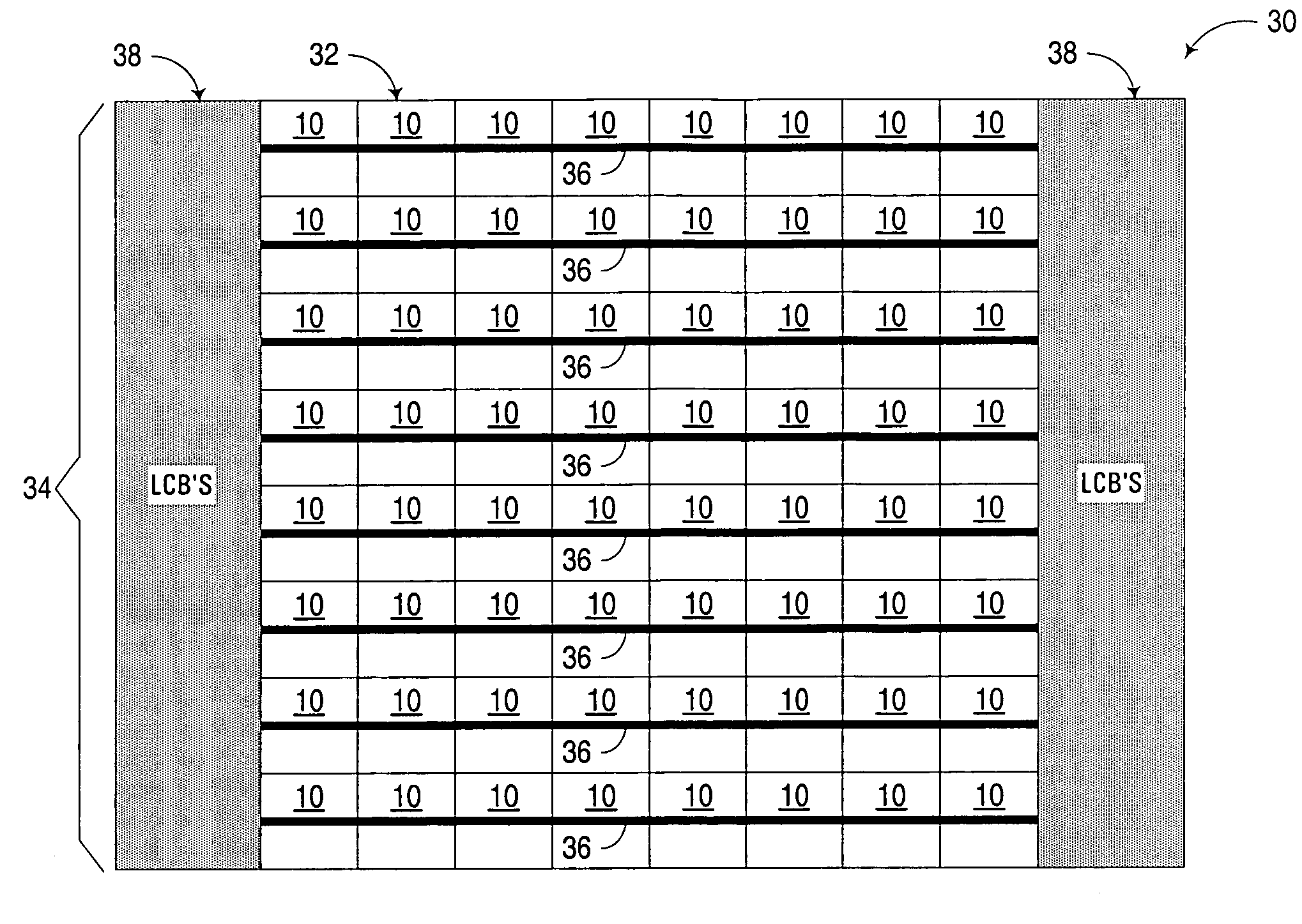
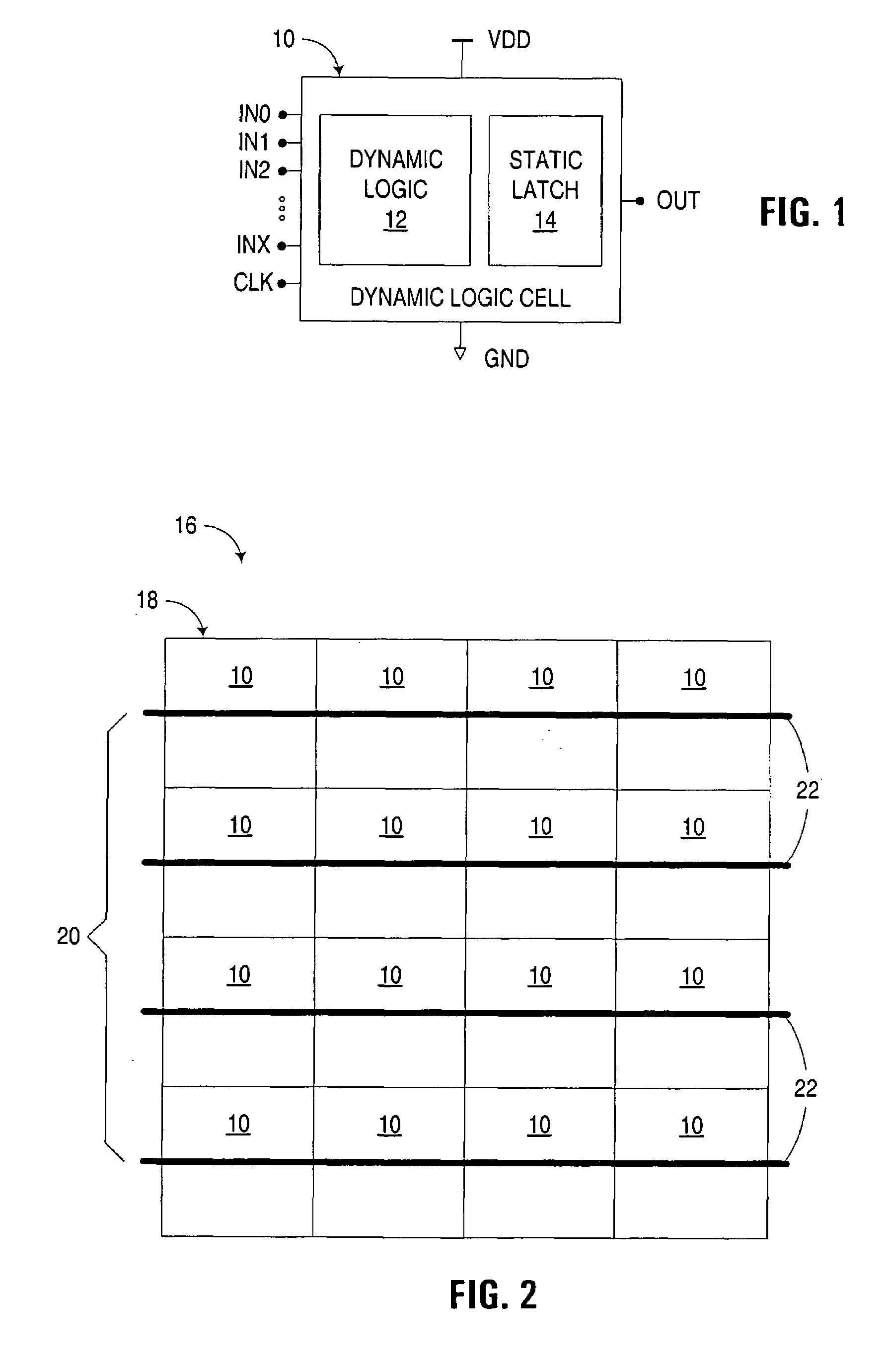
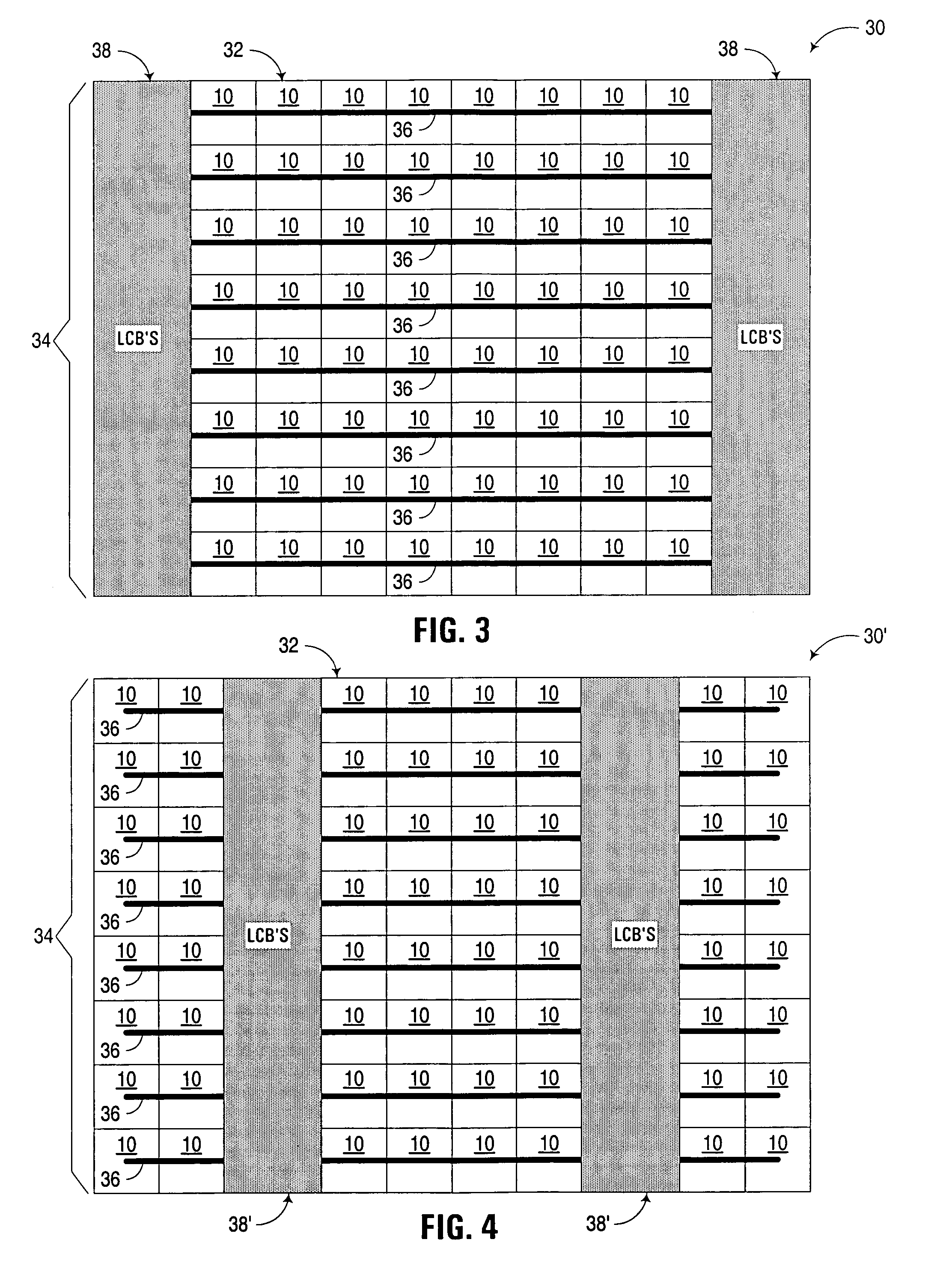
[0023]The embodiments discussed herein utilize an array of functionally interchangeable dynamic logic cells to implement application specific logic functions in an integrated circuit design.

[0024]A functionally interchangeable dynamic logic cell consistent with the invention incorporates an output latch implemented using static logic to capture a logic state generated by a dynamic logic circuit at a dynamic node in the cell. By doing so, the cell offers a stable storage element.

[0025]In addition, dynamic logic cells consistent with the invention are functionally interchangeable to the extent that each logic cell implements the same logical function such that any logic cell in an array may be substituted for another logic cell in the array when mapping the desired application specific logic function to the array of logic cells. While in many embodiments each functionally interchangeable dynamic logic cell may be identical also in terms of physical design and layout, in other embodime...


PUM


Abstract

A circuit arrangement, integrated circuit device, apparatus, program product, and method utilize an array of functionally interchangeable dynamic logic cells to implement an application specific logic function in an integrated circuit design. Each functionally interchangeable dynamic logic cell is comprised of a dynamic logic circuit configured to generate an output as a function of a plurality of inputs, and an output latch that is configured to latch the output generated by the logic circuit. The array of functionally interchangeable dynamic logic cells are used to implement an application specific logic function within a specific logic design by routing a plurality of conductors between inputs and outputs of at least a subset of the functionally interchangeable dynamic logic cells.

Description

FIELD OF THE INVENTION[0001]The invention is generally related to integrated circuits and integrated circuit design, and in particular to synthesis of integrated circuit designs using standard logic cells.BACKGROUND OF THE INVENTION[0002]Electronic integrated circuits, or “chips” have become significantly more complex as circuit fabrication technologies have improved. It is not uncommon for integrated circuits to incorporate hundreds of millions of transistors, with a comparable number of interconnects, or signal paths, integrated together onto a single piece of silicon substrate no larger than the size of a coin. In addition, often the same functionality that once required multiple chips can now be integrated onto the same chip, a concept often referred to as “system-on-chip” technology.[0003]The design of integrated circuits has likewise become more difficult as complexity has increased. Whereas early chips were often designed gate by gate, more advanced integrated circuits incorp...

Claims


Application Information

Patent Timeline
Patent Type & Authority Patents(United States)
IPC IPC(8): G06F17/50
CPCG06F17/5036H03K19/1736H03K19/1772G06F30/367
Inventor TRETZ, CHRISTOPHE ROBERT
Owner MARVELL ASIA PTE LTD
Learn More