
Eureka
For R&D, Eureka makes reading and utilizing patents & technical documents easy.
Eureka AIR
Designed for self-driven R&D workflows. Generate viable solutions, solve complex R&D challenges, empower your innovation with AI.

Eureka Materials
Designed for material experts only. Revolutionize your material R&D, from search, analyze, to developing new materials.

TechResearch
Generate reliable direction feasibility study reports for your R&D in just a few steps.

TechSeek
Discover and master advanced knowledge NOW. Basics, ideas, possibilities, all at once.

TechMind
As an expert in R&D Theories, TechMind can generates customized viable solutions instantly.

TechRisk
Analyze your overall solution with one click, know your potential R&D risks in advance.

TechMonitor
Get weekly tech updates, stay abreast of the latest tech innovations and key insights.
Shackle apparatus
- Summary
- Abstract
- Description
- Claims
- Application Information
AI Technical Summary
Benefits of technology
Problems solved by technology
Method used
Image

Examples
Embodiment Construction
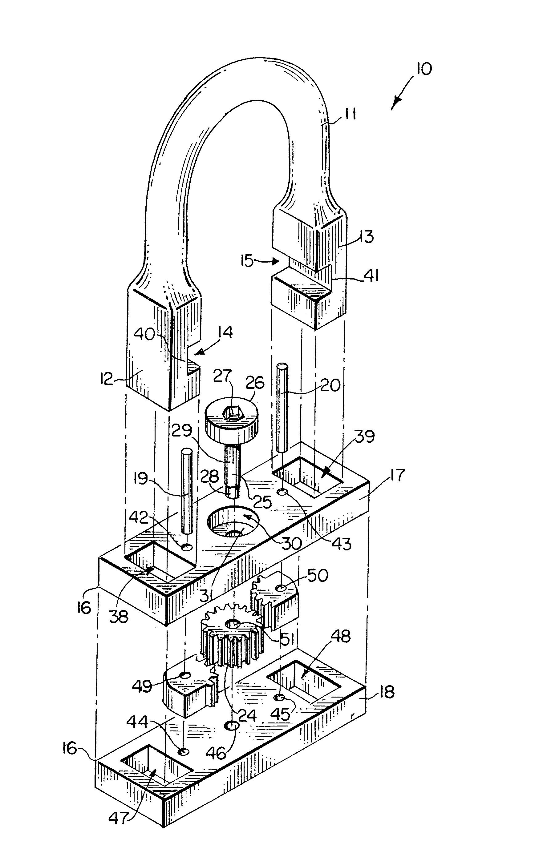
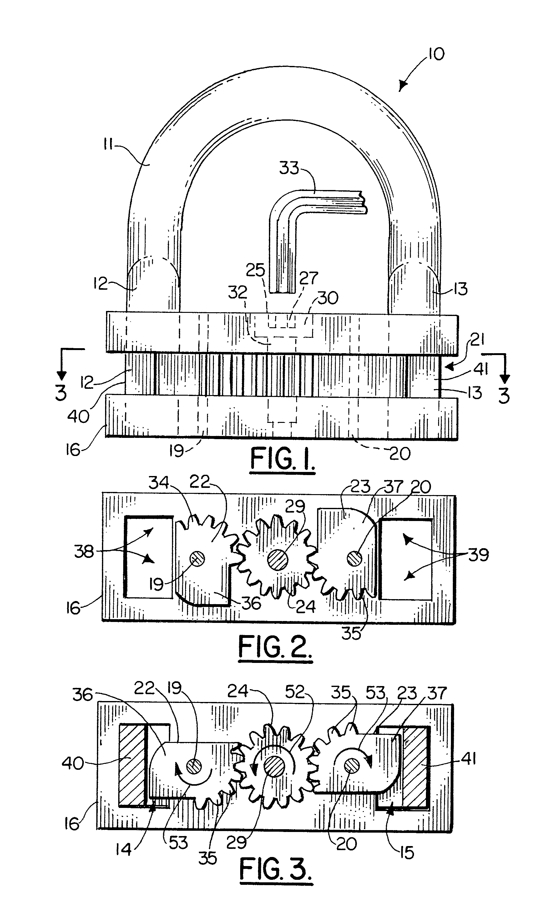
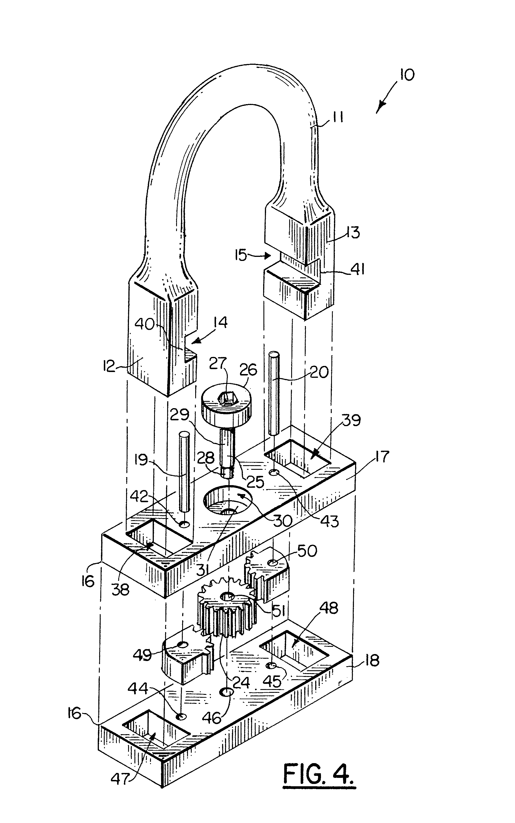
[0038]FIGS. 1-9 show the preferred embodiment of the apparatus of the present invention designated generally by the numeral 10. Shackle apparatus 10 provides a bow 11 having bow end portions 12, 13. Each of the bow end portions 12, 13 is slotted, the end portion 12 providing slot 14. The end portion 13 has a slot 15. Next to the slots 14, 15 the bow ends 12, 13 thus provide narrowed parts 40, 41 respectively.
[0039]A pin assembly 16 is provided that detachably connects to the bow 11. The pin assembly 16 in FIGS. 1-4 includes an upper plate 17, a lower plate 18 and connecting pins 19, that hold the plates 17, 18 in a spaced apart relation with a gap 21 therebetween as shown in FIGS. 1 and 5.
[0040]In order to secure the bow 11 to the pin assembly 16, a pair of locking members 22, 23 are provided. The locking members 22, 23 are rotatably mounted to pins 19, 20 at openings 49, 50 (see FIG. 4). The locking members 22, 23 rotate between an unlocked position (FIG. 2) and a locking position ...
PUM
 Abstract
Description
Claims
Application Information
 - R&D Engineer
- R&D Manager
- IP Professional
- Industry Leading Data Capabilities
- Powerful AI technology
- Patent DNA Extraction
Browse by: Latest US Patents, China's latest patents, Technical Efficacy Thesaurus, Application Domain, Technology Topic, Popular Technical Reports.
© 2024 PatSnap. All rights reserved.Legal|Privacy policy|Modern Slavery Act Transparency Statement|Sitemap|About US| Contact US: help@patsnap.com