
Electromechanical apparatus for dispensing volatile substances with single dispensing mechanism and cartridge for holding multiple receptacles

a technology of electronic equipment and volatile substances, which is applied in the direction of atomized substances, applications, disinfection, etc., can solve the problems of user's olfactory sense being desensitized to the scent, atomization devices significantly increasing the cost of manufacture, and primitive technology generally exhibit a variety of performance limitations, etc., to achieve high practicability, low cost, and high degree of operational flexibility

Inactive Publication Date: 2008-06-24
SC JOHNSON & SON INC
View PDF328 Cites 95 Cited by
  • Summary
  • Abstract
  • Description
  • Claims
  • Application Information

AI Technical Summary

Benefits of technology

[0011]The present invention provides a compact electromechanical dispenser that is capable of dispensing a variety of volatile substances with a significant degree of operational flexibility, subject to the control of a user, that can be operated in a highly convenient, simple manual fashion and can also be provided with the capability of operating in an automated manner, and that can be manufactured at a low cost. Specifically, the present invention provides an electromechanical dispenser of a volatile substance having a cartridge holding multiple receptacles for containing volatile substances, respectively, and a single dispensing mechanism that can be engaged with any of the receptacles to dispense the volatile substance contained therein. According to the invention, the receptacles can be moved, for example, by rotation of the cartridge holding the receptacles, such that any individual receptacle can be brought into a dispensing position in which the volatile substance can be dispensed, while the other receptacles are kept in non-dispensing positions. A cam feature is provided whereby, as the cartridge is rotated in order to disengage a first receptacle from the dispensing mechanism and engage a second receptacle with the dispensing mechanism, the rotation of the cartridge causes the dispensing mechanism to disengage from the first receptacle, to be kept out of the path of motion of the receptacles during rotation, and to engage the second receptacle when the second receptacle is properly aligned with the dispensing mechanism. Also provided are manual rotation levers for rotating the cartridge, which levers also provide feedback to the user as to whether the receptacles are properly aligned (the receptacles are properly aligned when any one receptacle is properly aligned with the dispensing mechanism). By providing an apparatus capable of holding multiple receptacles, integrated, via a cam feature, with a single dispensing mechanism, the present invention is able to keep manufacturing costs to a minimum while yet providing ample operational flexibility (including the ability to dispense a variety of volatile substances) in a convenient, simple, user-friendly format.
[0016]The cartridge comprises a cam feature such that, when the cartridge rotates, the pivot arm causes the dispenser to alternately disengage and engage successive reservoirs. The cam feature comprises a cut-away tubular portion having on a longitudinal end thereof a circumferential cross-sectional surface that alternately rises and falls along the circumference. The pivot arm is connected to the dispenser, and the pivot arm abuts the circumferential cross-sectional surface of the cut-away tubular portion such that, when the cartridge is rotated, the pivot arm alternately rises and falls, causing the dispenser to move alternately between a disengagement position and an engagement position.
[0018]Each of the reservoirs includes or is coupled with a liquid delivery member, which may be a wick. By virtue of the alternately rising and falling circumferential cross-sectional surface, the atomizer assembly is maintained at a position above the liquid delivery member of a next-to-be engaged reservoir, before the atomizer assembly engages the next-to-be engaged reservoir, and the atomizer assembly drops down upon the liquid delivery member to engage the next-to-be engaged reservoir, whereby collision, improper engagement and non-engagement of the liquid delivery member with the atomizer assembly, due to vertical misalignment therebetween, are prevented.
[0021]According to a fifth aspect of the present invention, the apparatus according to the fourth aspect is provided, wherein the housing has a circumferential surface provided with at least one concave portion, and the at least one handle is provided with a convex portion that fits into the concave portion. As the cartridge is rotated, the concave portion is rotationally brought into alignment with the convex portion at the same time as one of the reservoirs is brought into an engagement position. The aligning of the concave portion with the convex portion thus provides visual, auditory and / or tactile feedback to a user of the apparatus that one of the reservoirs is in an engagement position.

Problems solved by technology

While it is of course possible to design a dispenser devoid of electrical or even mechanical components, inasmuch as many volatile substances of interest will spontaneously vaporize, in practice, such technologically primitive devices generally exhibit a variety of performance limitations, particularly with respect to the ability to vary the modes of, or otherwise control, operation of the device.
In regard to fragrance dispensing devices, it is known that if a user is continually exposed to the same odor or fragrance, the user's olfactory sense can become desensitized to the scent.
While such an apparatus is capable of providing enhanced performance, for example, in the way of a variety of modes, fragrance combinations, and control or programming, the provision of multiple atomization devices significantly increases the cost of manufacture.

Method used


Image

  • Electromechanical apparatus for dispensing volatile substances with single dispensing mechanism and cartridge for holding multiple receptacles
  • Electromechanical apparatus for dispensing volatile substances with single dispensing mechanism and cartridge for holding multiple receptacles
  • Electromechanical apparatus for dispensing volatile substances with single dispensing mechanism and cartridge for holding multiple receptacles

Examples


Embodiment Construction

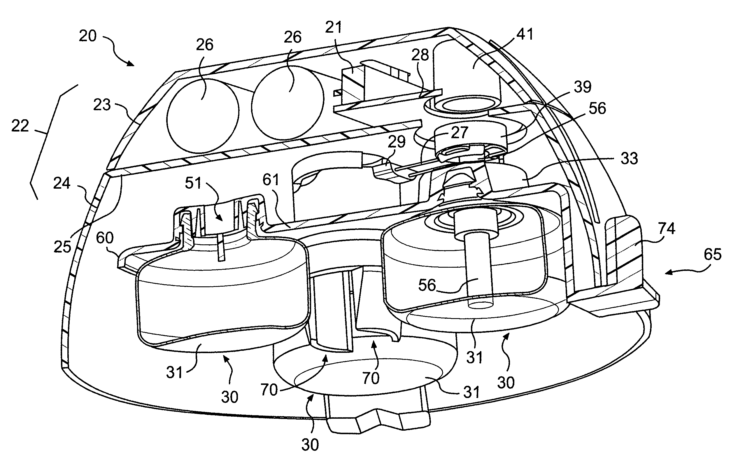
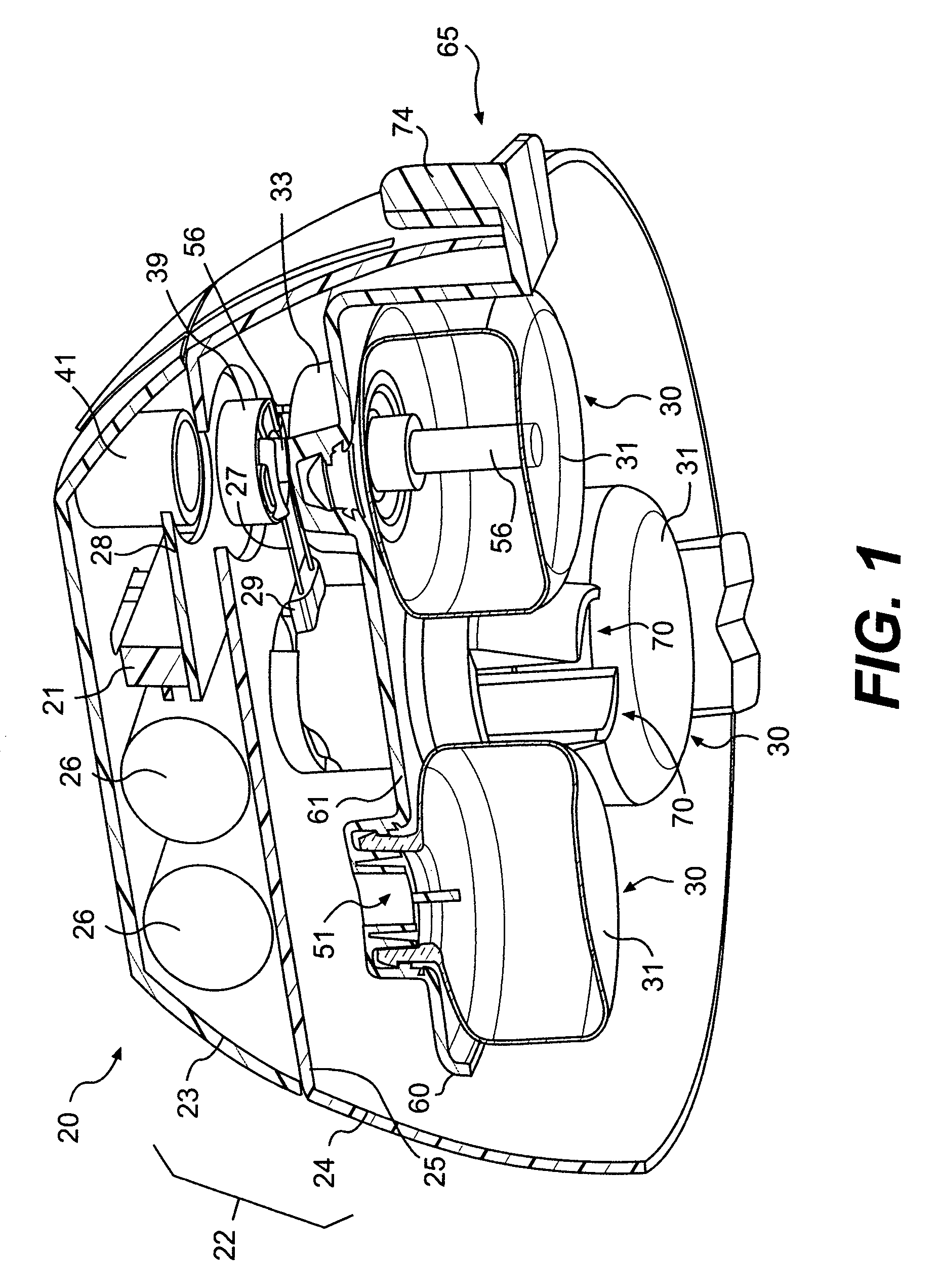
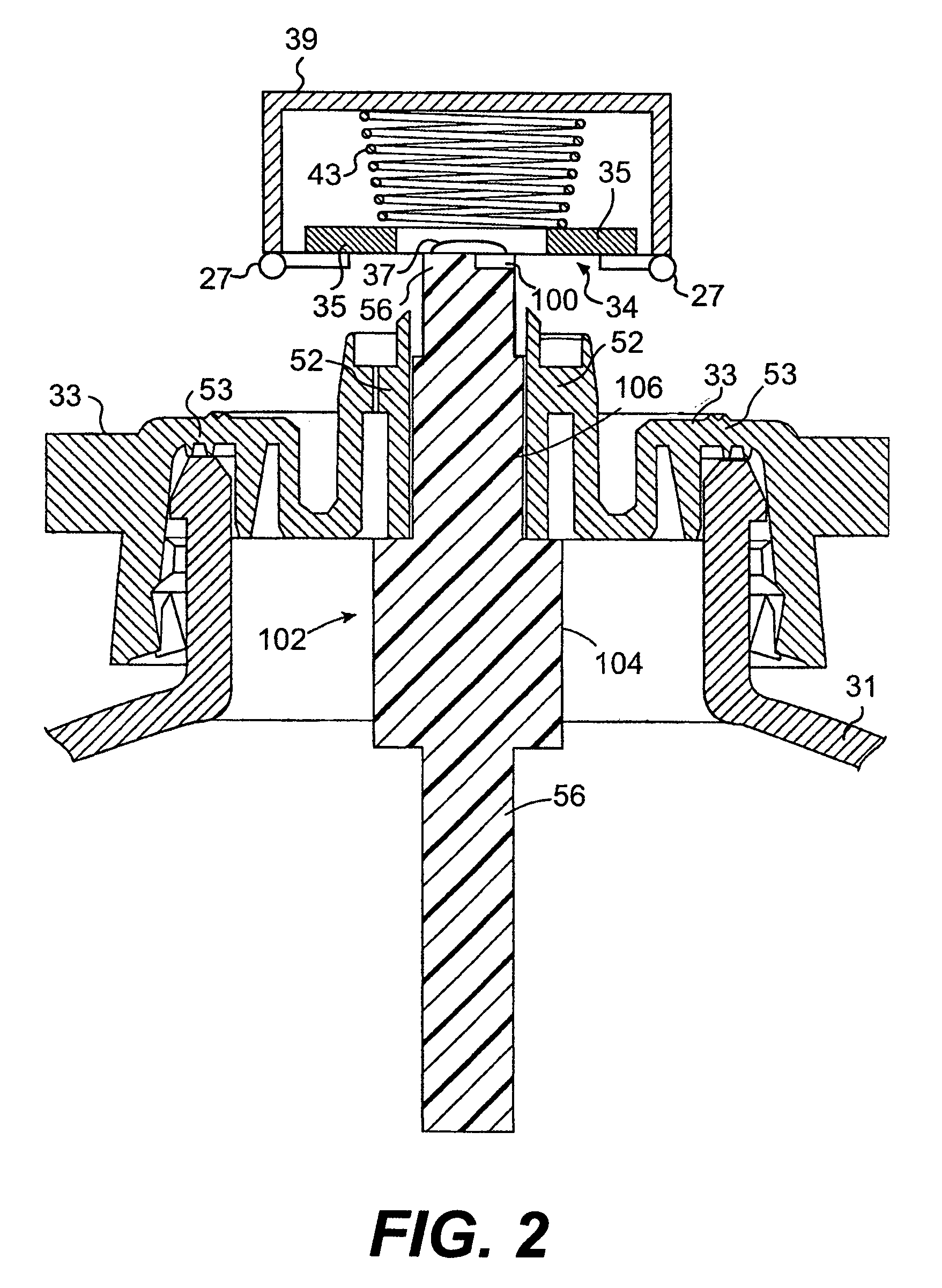
[0047]The structure and operation of an electromechanical dispenser according to a preferred embodiment of the present invention will be explained with reference to the accompanying drawings. The reader is directed initially to FIGS. 1, 2, 8A and 8B. According to a preferred embodiment, the electromechanical dispenser is a piezoelectrically actuated vibratory type liquid atomization apparatus 20 generally comprising an atomizer assembly 34 (see FIGS. 8A and 8B) and a cartridge 60 holding a plurality of reservoir assemblies 30. The atomizer assembly 34 comprises a piezoelectric actuator element 35 and an orifice plate 37. Each reservoir assembly 30 includes a liquid container 31 containing fluid and a wick 56. (The liquid container 31 or the reservoir assembly 30 may be referred to as a receptacle or a reservoir.) The cartridge 60 can be moved, e.g., rotated, so as to place any reservoir assembly 30 in engagement with the atomizer assembly 34. When a given reservoir assembly 30 is en...


PUM


Abstract

An apparatus for dispensing a volatile substance includes an electromechanical dispenser attached to a pivot arm, and a cartridge for holding a plurality of reservoirs each containing a volatile substance. The cartridge is rotatable such that any one of the reservoirs can be positioned in an engagement position, in which the volatile substance can be dispensed. The cartridge has a cam feature consisting of a contoured circumferential surface that alternately rises and falls. The pivot arm operates in tandem with the cam feature such that, when the cartridge is rotated, the dispenser alternately engages and disengages from successive reservoirs, and remains out of the path of motion traversed by the reservoirs as the cartridge rotates from one engagement position to a subsequent engagement position. The electromechanical dispenser may be a piezoelectrically actuated vibratory type liquid atomization apparatus, and the volatile substance may be a fragrance.

Description

CROSS-REFERENCE TO RELATED APPLICATIONS[0001]This application claims the benefit of, and incorporates by reference, U.S. Provisional Patent Application No. 60 / 583,604, filed Jun. 30, 2004, and U.S. Provisional Patent Application No. 60,670,519, filed Apr. 12, 2005.BACKGROUND OF THE INVENTION[0002]1. Field of the Invention[0003]This invention relates to an electromechanical dispenser for dispensing a volatile substance, such as a piezoelectrically actuated vibratory type liquid atomization apparatus for emitting a fragrance. More particularly, it relates to such a dispenser having a single dispensing mechanism, such as a single atomization device, and a carousel that holds multiple receptacles each containing a volatile fragrant substance, the single atomization device being capable of engaging any of the receptacles by means of movement of the receptacles, such as by rotation of the carousel relative to the atomization device.[0004]2. Description of the Related Art[0005]Electromecha...

Claims


Application Information

Patent Timeline
Patent Type & Authority Patents(United States)
IPC IPC(8): B05B1/08A61M11/00B05B9/00B05B9/03
CPCA01M1/205A61L9/127A61L9/14B05B17/0646Y10S261/88
Inventor JAWORSKI, THOMAS
Owner SC JOHNSON & SON INC
Learn More