Rotating barrier

a technology of rotating barriers and rotors, applied in the field of rotating barriers, can solve problems such as affecting comfort when passing, and achieve the effects of not affecting comfort, increasing the passing speed of users, and reducing the force that acts

Active Publication Date: 2008-07-01
SKIDATA AG
View PDF13 Cites 6 Cited by
  • Summary
  • Abstract
  • Description
  • Claims
  • Application Information

AI Technical Summary

Benefits of technology

[0006]The blocking arm can in fact come in contact with the user during the second partial rotation. However, if the rotational speed in the second partial rotation is not increased, this does not result in an impairment of comfort, even if the user walks very slowly. The torque is composed of the force and the lever arm. When the blocking arm is rotated upward out of its downward pointing release position, it first touches the slowly walking person at a large distance from its rotation axis, i.e. with a long lever arm, and thus only lightly. This light touching has the psychological effect of increasing the user's passing speed and thus decreasing the force that acts on the initially slowly walking user due to the blocking arm.
[0007]According to the invention, there is the possibility here of making the rotational speed in the second partial rotation lower in order to further reduce the force of the blocking arm acting on a slowly walking user, but without impairing the reliability of person singling.
[0008]Further, according to the invention, the rotation angle in the second partial rotation can be 120° or more, in particular about 180°. This prevents the blocking arm from protruding partly into the gateway in the release position and thus impairing the comfort when passing.
[0009]Preferably, the rotation axis of the blocking element is inclined relative to the horizontal by 30° to 40°, while the angle of the blocking arm relative to the rotation axis of the blocking element is preferably 40° to 50°. Thus, in its downward rotated release position the blocking arm can extend into the gateway at an angle of no more than 10° relative to the vertical, preferably even out of the gateway, i.e. obliquely downward away from the gateway. Thus, the room at the gateway can even increase in the release position of the rotating arm from its rotation axis downward, thereby obtaining a particularly comfortable passage.

Problems solved by technology

This prevents the blocking arm from protruding partly into the gateway in the release position and thus impairing the comfort when passing.

Method used


Image

  • Rotating barrier
  • Rotating barrier

Examples


Embodiment Construction

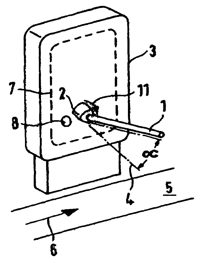
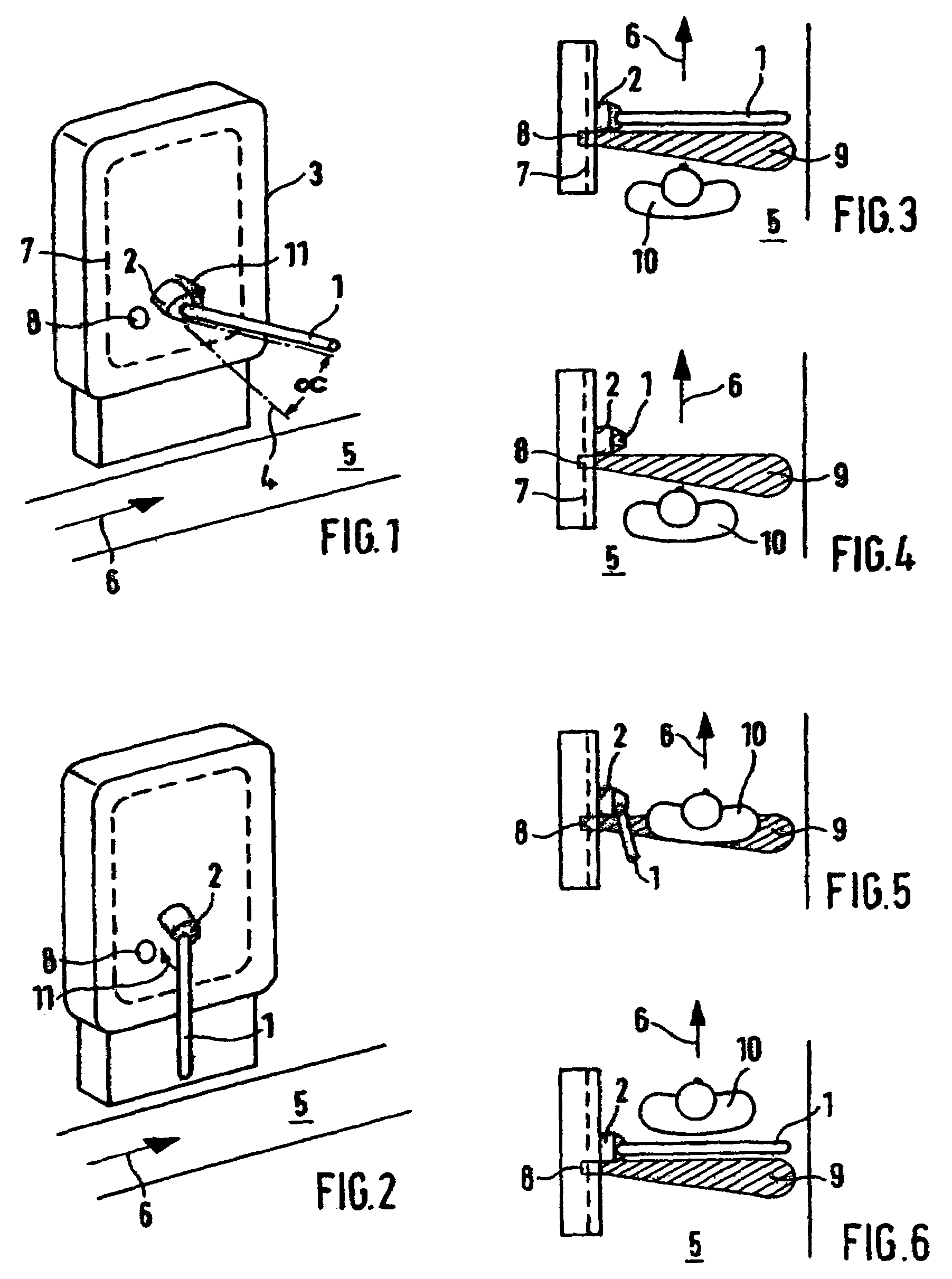
[0017]According to FIGS. 1 and 2, the rotating barrier has a blocking element 2 formed as a rotating member with, a blocking arm 1, said element being driven by a motor (not shown) in a housing 3. The rotation axis 4, shown by dashed lines, of the blocking element 2 is inclined downward from the horizontal by an angle α of about 35°. The angle that the rotation axis 4 encloses with the blocking arm 1 can be somewhat larger, being for example 45°.

[0018]While the blocking arm 1 assumes an approximately horizontal position and thus blocks the gateway 5 in the direction of the arrow 6 in the blocking position shown in FIG. 1, it is swiveled approximately vertically downward in the release position shown in FIG. 2.

[0019]The housing 3 also receives the other components, such as the mounting and the gearing and the electronics for operation of the motor and of the blocking element 2. The housing 3 further contains an antenna 7, shown by dashed lines, for an RFID reader module (not shown) f...


PUM


Abstract

A rotating barrier for a gateway (5) has a rotatable blocking element (2) having a single blocking arm (1) which blocks the gateway (5) in the blocking position and is rotated between the blocking positions by 360° in each case. Further provided are an access authorization reader (7) and a people sensor (8) whose detection area (9) is located in front of the blocking arm (1) in the blocking position thereof.

Description

FIELD OF THE INVENTION[0001]This invention relates to a rotating barrier having a blocking element.BACKGROUND OF THE INVENTION[0002]A rotating barrier is known from EP 804676 B1. The detection area of the disclosed people sensor is located accordingly behind the blocking arm when the arm is in its blocking position. Compared to a conventional rotating barrier with three blocking arms, the single blocking arm substantially improves the comfort when passing, in particular when one is carrying objects such as skis, ski poles, bags and the like. However, it is disadvantageous that after the first partial rotation of the blocking arm to the release position, which has been triggered by a valid access authorization, a following person without access authorization, can pass through the gateway along with the preceding person before the gateway is blocked again by the second partial rotation of the blocking arm. To remedy this, EP 804676 B1 proposes making the rotation angle of the second p...

Claims


Application Information

Patent Timeline
Patent Type & Authority Patents(United States)
IPC IPC(8): E06B11/08G07C9/00G07C9/02
CPCE06B11/08G07C9/025G07C9/00007G07C9/15G07C9/20
Inventor WALLERSTORFER, KURTPONERT, GREGOR
Owner SKIDATA AG
Why Eureka
Try Eureka