Fixing device

a technology of fixing device and fixing plate, which is applied in the direction of electrographic process, electric/magnetic/electromagnetic heating, instruments, etc., can solve the problems of difficult to secure high input power, and achieve the effect of high electric power

Active Publication Date: 2010-03-23
KONICA MINOLTA BUSINESS TECH INC
View PDF8 Cites 2 Cited by
  • Summary
  • Abstract
  • Description
  • Claims
  • Application Information

AI Technical Summary

Benefits of technology

[0008]An object of the present invention is to provide a fixing device allowing high electric power to be inputted to a fixing roller through a magnetic flux generating section when a drive frequency is high.
[0011]In the fixing device of the present invention, the high frequency power supply circuit applies voltage having a certain drive frequency to the series resonant circuit, which makes the fixing roller generate heat through the magnetic flux generating section. In the series resonant circuit, which is composed of the coil and the capacitor, an impedance Z is minimized when the drive frequency and a resonance frequency are equal to each other. Thereby, a current flow is maximized, which maximizes electric power inputted into the fixing roller through the magnetic flux generating section (this is called “maximum input power”). Therefore, high electric power can be inputted even when the heat generating layer of the fixing roller has a thickness as thin as 100 μm or less and when the drive frequency is thereby set high. Thus, it is possible to achieve high heat generation efficiency and high input power at the same time. As a result, the device is warmed up in a short period of time, and a paper passing speed is increased.
[0012]The pressure roller is preferably provided with a nip section brought into pressure-contact with the outer peripheral surface of the fixing roller. In this case, sheets can smoothly be transported through the nip section, and therefore, the quality of fixed images can be enhanced.

Problems solved by technology

If the drive frequency f is made higher, then the turn-on period T of the switching element is shortened, which makes it difficult to secure high input power.

Method used


Image

  • Fixing device
  • Fixing device
  • Fixing device

Examples


Embodiment Construction

[0030]The present invention will be described hereinbelow in conjunction with the embodiments with reference to the drawings.

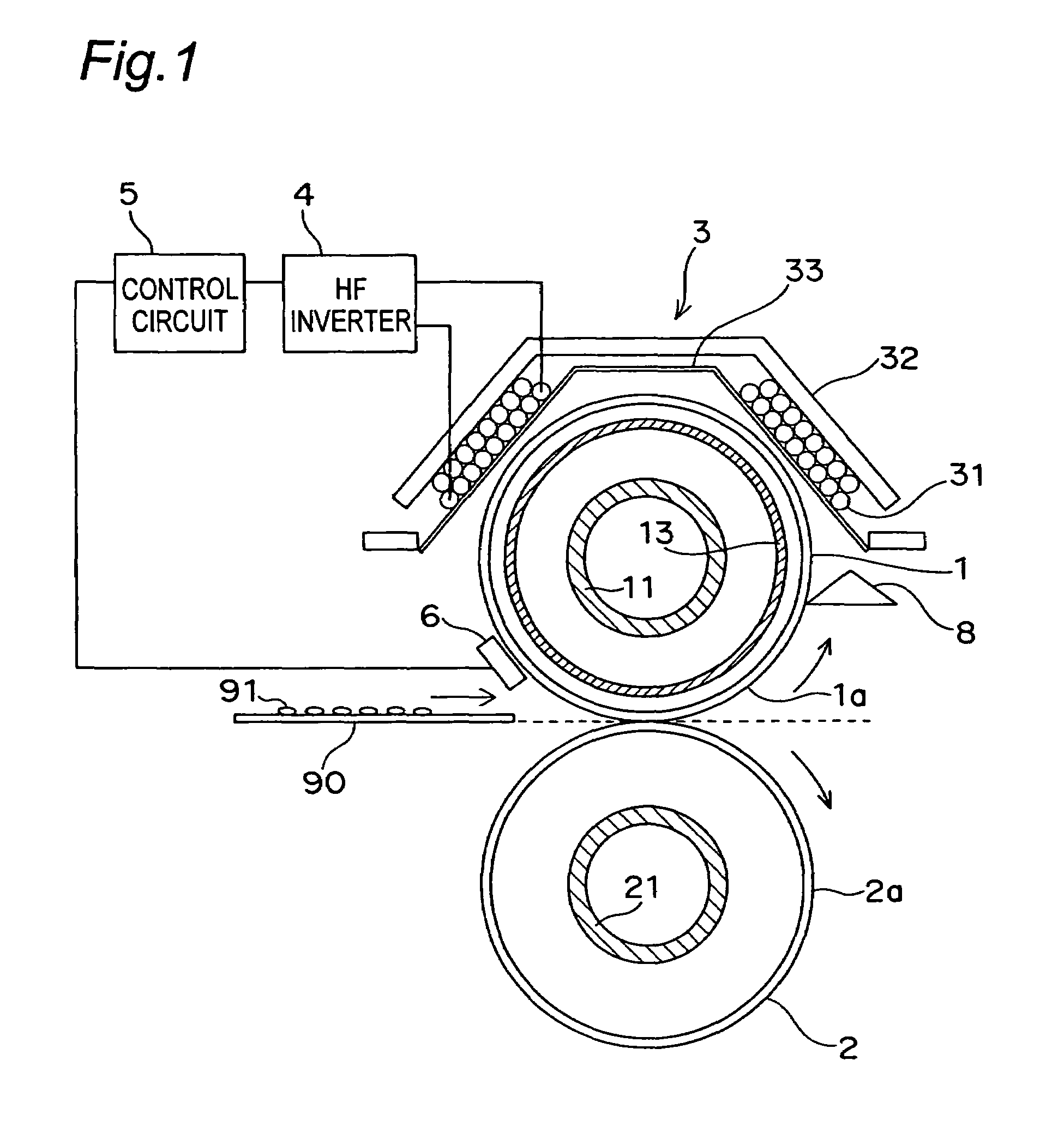
[0031]FIG. 1 shows a cross sectional structure of a fixing device in one embodiment for laser color printers.

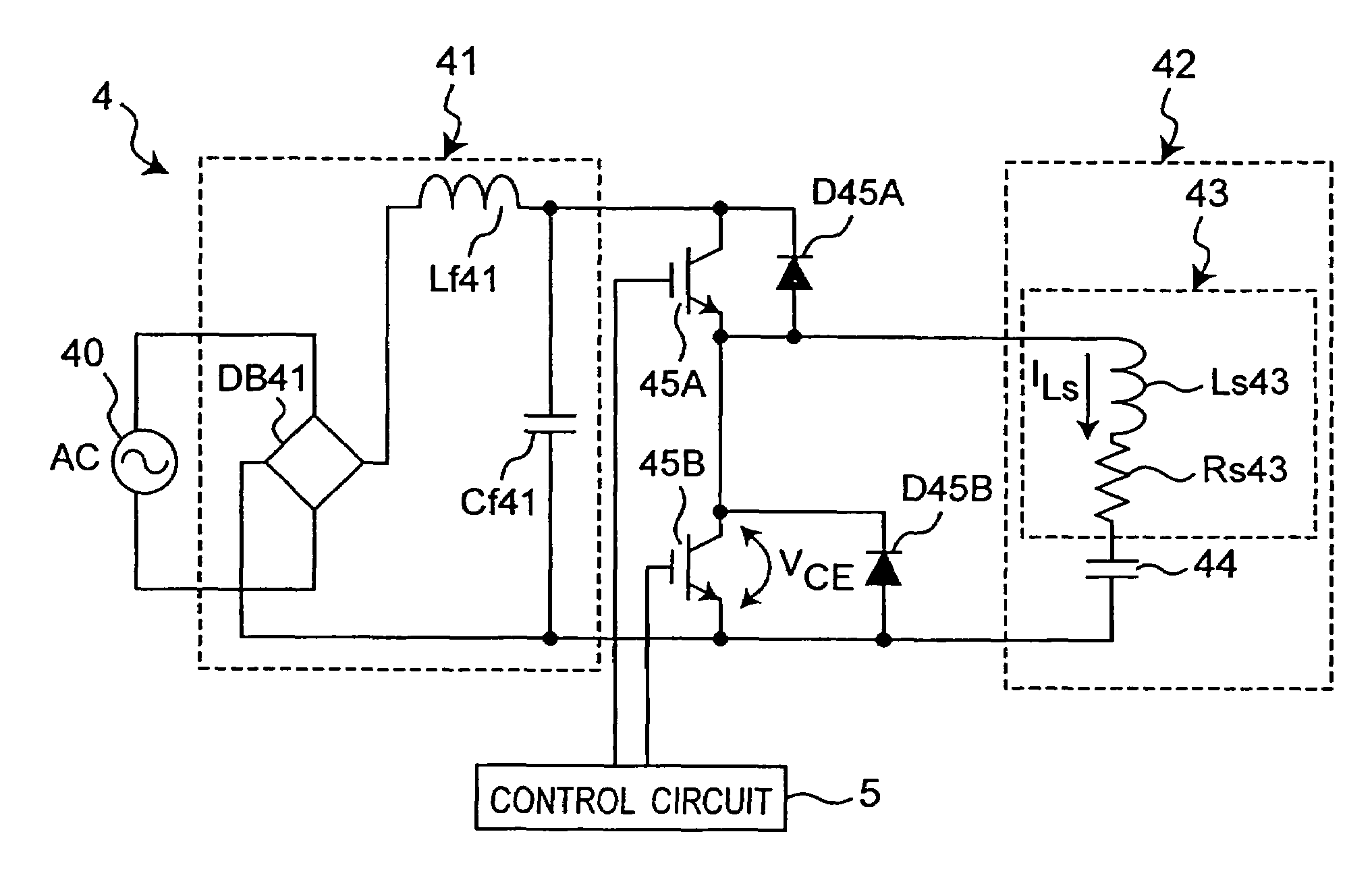
[0032]The fixing device mainly includes a fixing roller 1, a pressure roller 2, a magnetic flux generating section 3, a high frequency (HF) inverter 4 as a high frequency power supply circuit, and a control circuit 5. Reference numeral 6 denotes a temperature sensor, reference numeral 8 denotes a separation nail, and reference numeral 90 denotes a paper sheet as a sheet.

[0033]The fixing roller 1 and the pressure roller 2, which are cylindrical members vertically extending with respect to a sheet showing FIG. 1, are disposed vertically parallel to each other. Both ends of each of the rollers are rotatably supported by an unshown bearing member. The pressure roller 2 is biased toward the fixing roller 1 by an unshown pressing mechanism with use of a sprin...


PUM


Abstract

A fixing device includes a magnetic flux generating section having a coil which generates a magnetic flux when applying current, a fixing roller having a heat generating layer having a thickness of 100 μm or less formed along an outer peripheral surface of the fixing roller for generating heat through electromagnetic induction by the magnetic flux, a capacitor connected in series to the coil to constitute a series resonant circuit, and high frequency power supply circuits for applying voltage having a certain drive frequency to the series resonant circuit so as to make the fixing roller generate heat through the magnetic flux generating section. An image is fixed onto a sheet, which is transported in a state of being in pressure-contact with the outer peripheral surface of the fixing roller, by heat from the heat generating layer of the fixing roller.

Description

CROSS-REFERENCE TO RELATED APPLICATIONS[0001]This application is based on application No. 2005-340195 filed in Japan, the entire content of which is hereby incorporated by reference.BACKGROUND OF THE INVENTION[0002]The present invention relates to a fixing device, and more particularly relates to a fixing device for fixing images on a sheet with use of heat from a fixing roller heated by the electromagnetic induction heating method.[0003]A fixing device of this kind has been known as described in JP 2000-214702 A or JP 2000-214713 A. The fixing device has a fixing roller and a pressure roller in pressure-contact with each other, wherein an electromagnetic induction heat generating layer (hereinbelow referred to as “heat generating layer”) of the fixing roller is heated by a magnetic flux generated in a magnetic flux generating section. Then, a recording member carrying an unfixed image is held and transported by a nip section, which is made up of a pressure-contacted portion of the ...

Claims


Application Information

Patent Timeline
Patent Type & Authority Patents(United States)
IPC IPC(8): G03G15/20
CPCG03G15/2057
Inventor IWAHASHI, HARUOOHNO, YASUHIROKAMODA, YUJIMASUDA, TOMOHIKO
Owner KONICA MINOLTA BUSINESS TECH INC
Why Eureka
Try Eureka