Method for retaining vertical impact of impacting mechanism and vertical-lift impact-cutting digger implementing same

A technology of a vertical lifting mechanism and an impact mechanism, applied in the field of machinery, can solve the problems of difficulty in realizing coal mining by turning the impact head back, reducing efficiency, and increasing consumption.

Inactive Publication Date: 2013-07-17
刘素华
View PDF0 Cites 15 Cited by
  • Summary
  • Abstract
  • Description
  • Claims
  • Application Information

AI Technical Summary

Problems solved by technology

[0004] Some impact head coal shearers also adopt rocker-type lifting mechanism to lift. When the impact head needs to be turned around, because the length of the impact head and the rocker arm is too large, it is difficult to turn the impact head for return mining in narrow coal lanes. , because the rocker arm uses swing to adjust the coal mining height, so when the impact head adjusts the upper and lower mining heights, the impact angle of the impact

Method used


Image

  • Method for retaining vertical impact of impacting mechanism and vertical-lift impact-cutting digger implementing same
  • Method for retaining vertical impact of impacting mechanism and vertical-lift impact-cutting digger implementing same
  • Method for retaining vertical impact of impacting mechanism and vertical-lift impact-cutting digger implementing same

Examples


Embodiment 1

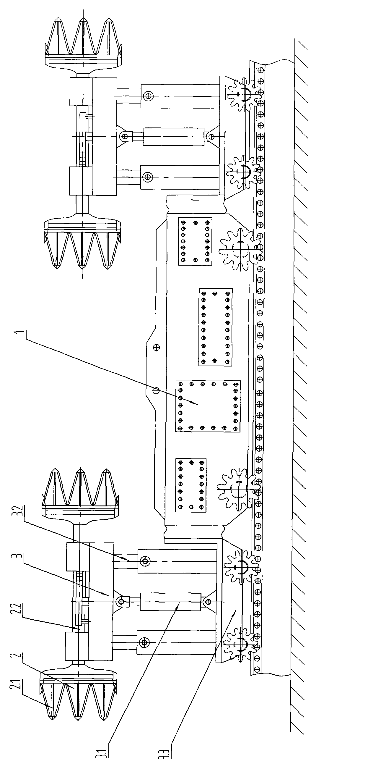
[0104] figure 1 It is the vertical lift punching excavator described in Embodiment 1. The vertical lifting punching mining machine includes a fuselage 1, an impact mechanism 2 and a vertical lifting mechanism 3. The impact mechanism 2 includes an impact head 2.1 and an impact guide 2.2. The vertical lifting mechanism 3 includes a vertical lifting drive device 3.1, a lifting moving part 3.2 and The supporting base 3.3, the lifting moving part 3.2 is movably connected with the supporting base 3.3, the supporting base 3.3 is connected with the fuselage 1, the impact mechanism 2 is arranged on the lifting moving part 3.2, the vertical lifting driving device 3.1 drives the lifting moving part 3.2 to move vertically up and down, and the lifting The moving part 3.2 drives the impact mechanism 2 to lift vertically.

Embodiment 2

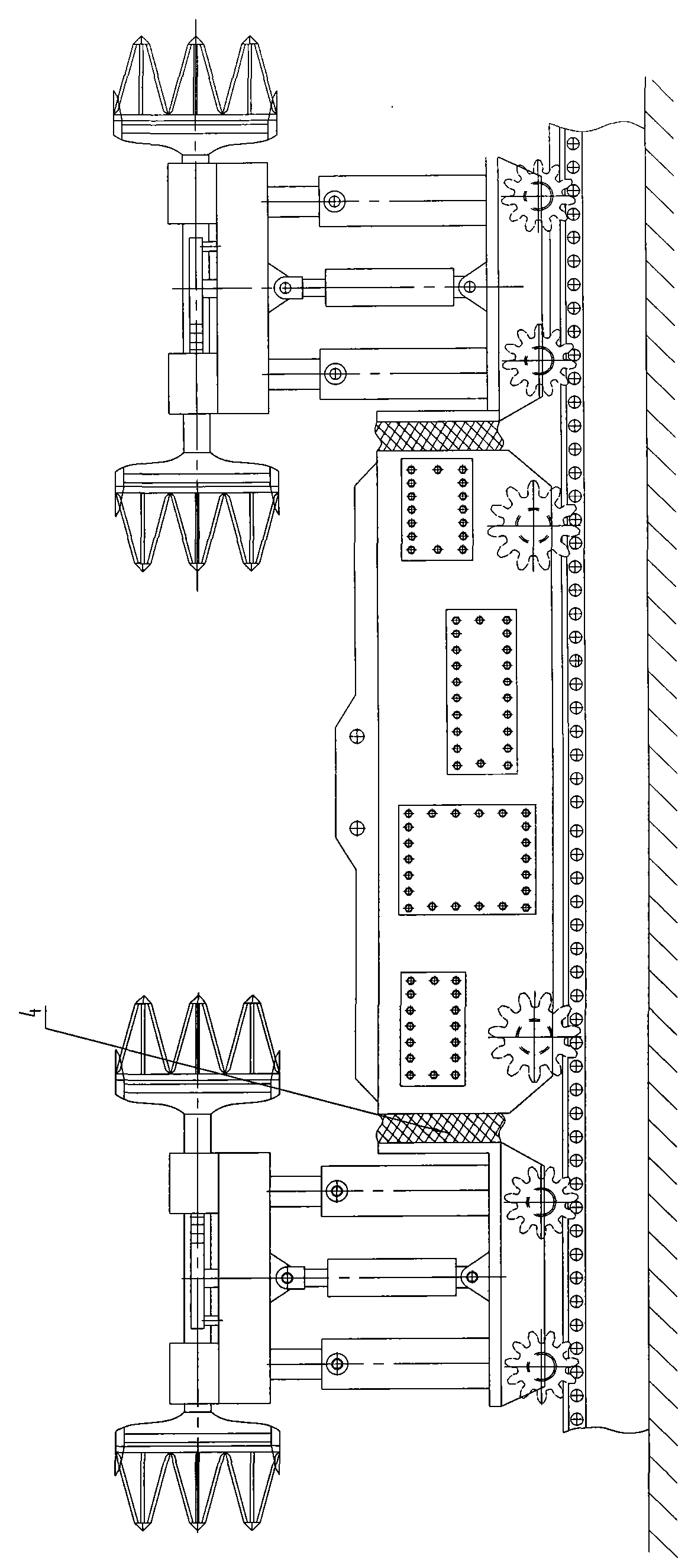
[0106] figure 2 It is the vertical lifting mechanism of the vertical lifting punching mining machine described in embodiment 2. What the vertical lifting driving device 3.1 of this vertical lifting mechanism 3 adopted is a spiral vertical lifting driving device.

[0107] Others are the same as embodiment 1.

Embodiment 3

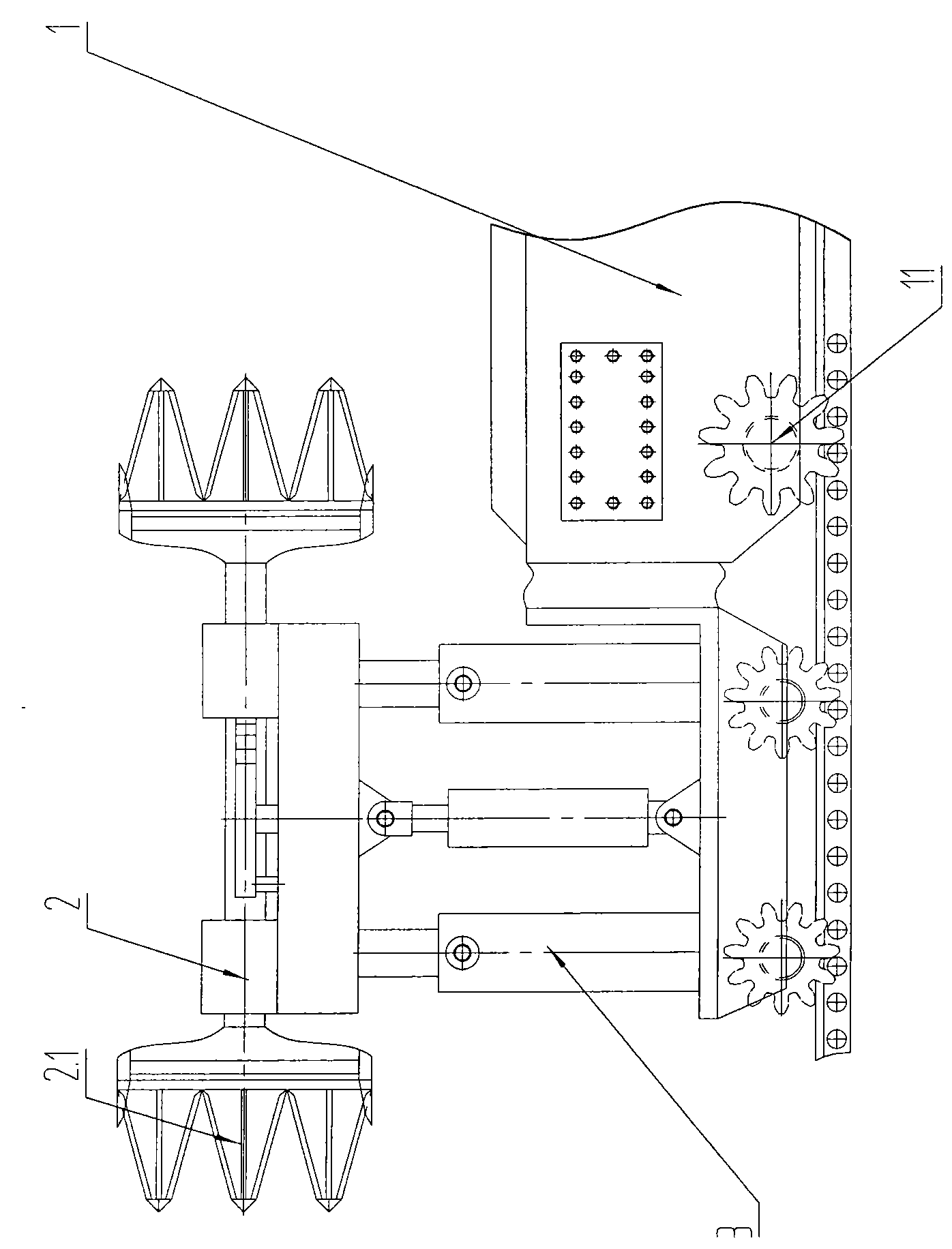
[0109] image 3 It is the vertical lifting mechanism of the vertical lifting punching mining machine described in embodiment 3. What the vertical lifting driving device 3.1 of this vertical lifting mechanism 3 adopted is the vertical lifting driving device of rope and rope reel.

[0110] The vertical lift drive device 3.1 can also be a hydraulic vertical lift drive device, a buckle lift device, a pneumatic vertical lift drive device, a sprocket chain vertical lift drive device or a rack and pinion vertical lift drive device.

[0111] Others are the same as embodiment 1.


PUM


Abstract

The invention specifically relates to a method for retaining vertical impact of an impacting mechanism and a vertical-lift impact-cutting digger implementing the method, belonging to the field of machinery, especially to the field of mining. The digger comprises a body, the impacting mechanism and a vertical lift mechanism, wherein the impacting mechanism comprises a guiding member and an impacting head, the vertical lift mechanism comprises a vertical lift driving unit, a lifting and moving part, a supporting seat and the like, the lifting and moving part is movably connected with the supporting seat, the supporting seat is connected with the body, the impacting mechanism is arranged on the lifting and moving part, the vertical lift driving unit drives the lifting and moving part to vertically move up and down, and the lifting and moving part drives the impacting mechanism to vertically rise and fall. The digger provided by the invention has the advantages of a long service life, a small amount of maintenance, high work efficiency, shortened body length and applicability to a complex usage occasion.

Description

technical field [0001] The invention belongs to the field of machinery, is applicable to the field of excavation, and in particular relates to a method for maintaining the vertical impact of an impact mechanism and a vertical lifting punching excavator implementing the method. Background technique [0002] At present, the lifting mechanism of coal shearer is basically rocker arm type. The higher the lifting height, the longer the rocker arm, which makes the whole machine bulky and complicated. Because the rocker arm is too long, it consumes a lot of power, and the rocker arm must be rigid. Heavy weight increases the waste of resources. [0003] When the power of the power box is transmitted to the roller on the top of the rocker arm, the distance is long, the structure is complicated, and the energy consumption is large, which increases the manufacturing difficulty and failure rate of the equipment. [0004] Some impact head coal shearers also adopt rocker-type lifting mech...

Claims


Application Information

Patent Timeline
IPC IPC(8): E21C25/02E21C31/08E21C25/04E21C31/02E21C35/04
Inventor 刘素华
Owner 刘素华
Why Eureka
Try Eureka