Semi-transmissive liquid crystal display device

a liquid crystal display and semiconductor technology, applied in static indicating devices, non-linear optics, instruments, etc., can solve the problems of increasing the manufacturing steps for forming the embedded retardation layer, deteriorating contrast, and decreasing contrast, so as to improve the display quality, increase the amplitude, and increase the drive frequency

Active Publication Date: 2011-01-06
NEC LCD TECH CORP
View PDF4 Cites 13 Cited by
  • Summary
  • Abstract
  • Description
  • Claims
  • Application Information

AI Technical Summary

Benefits of technology

[0024]In view of the above, it is an object of the present invention to provide a semi-transmissive LCD that has an improved display quality with no increase in drive frequency of a signal to be applied nor increase in amplitude of this signal while inhibiting an increase in dissipation power.
[0036]With the above configuration, it is possible to eliminate the need for enlarging the amplitude of a signal applied to the pixel electrodes or increasing the drive frequency of the signal applied to the common electrode and so improves the display quality of a semi-transmissive LCD while inhibiting an increase in dissipation power.

Problems solved by technology

If the embedded retardation layer described in the Related Art Patent Document 1 is used, a problem occurs in that manufacturing steps for forming this embedded retardation layer will be increased greatly.
Moreover, another problem occurs in that wavelength dispersiveness of the embedded retardation layer will disable realizing complete black when the reflective region is in the black display condition and so deteriorate contrast.
On the other hand, if the retardation film described in the Related Art Patent Document 2 is used, a problem occurs in that in the transmissive region, the liquid crystal layer will have a smaller gap margin to resultantly decrease contrast and a viewing angle against changes in gap of the liquid crystal layer, thereby disabling sufficiently obtaining high contrast and wide-viewing angle characteristics in the lateral field mode.
However, there are a few problems in lateral field mode LCDs of the Related Art Patent Documents 3 and 4 in which a driving method is improved.
However, even those tentative schemes have the following problems.

Method used


Image

  • Semi-transmissive liquid crystal display device
  • Semi-transmissive liquid crystal display device
  • Semi-transmissive liquid crystal display device

Examples


first exemplary embodiment

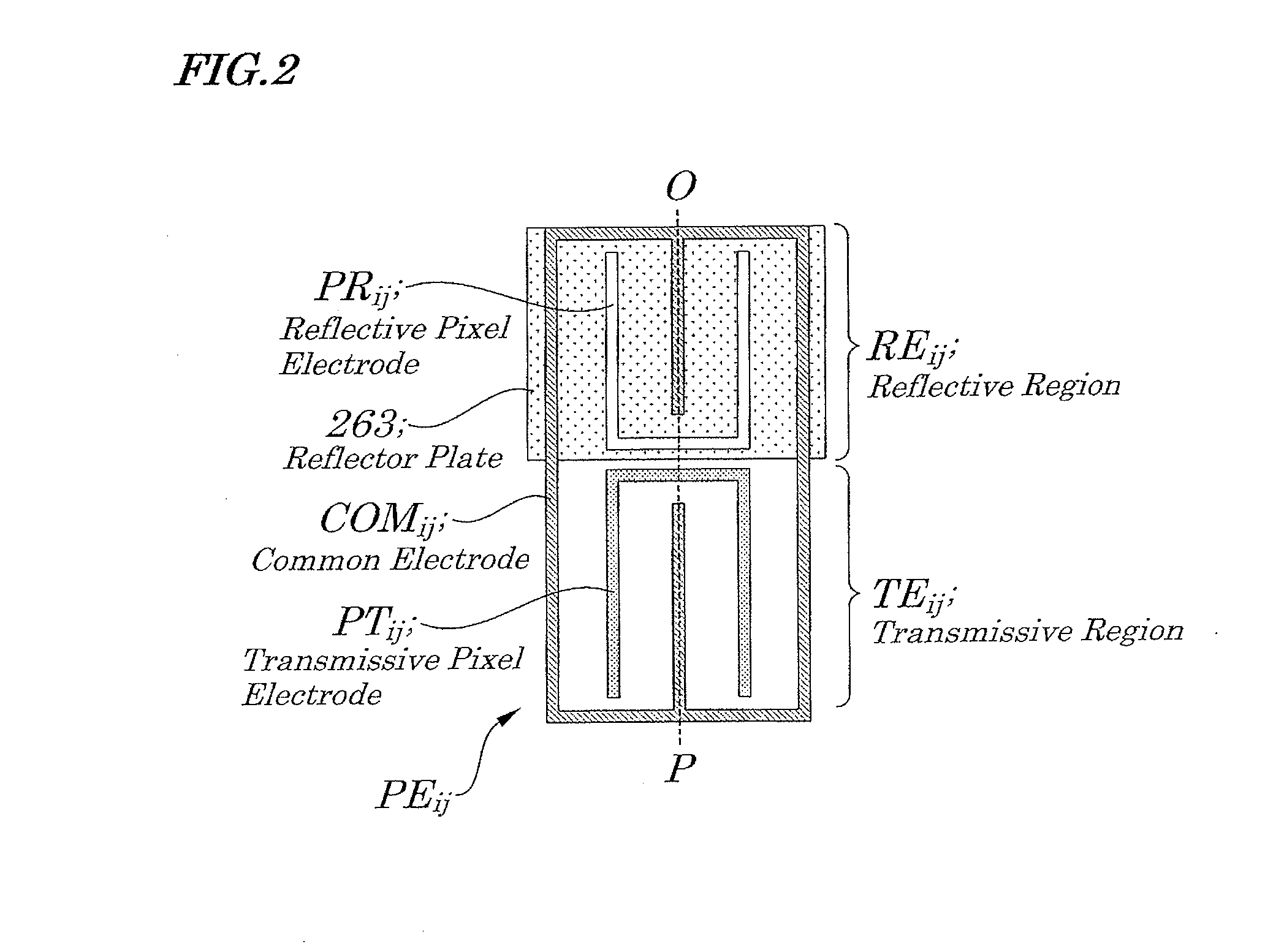
[0055]According to a first exemplary embodiment of the present invention, there is provided a semi-transmissive liquid crystal display device including: a plurality of unit pixels arranged in a form of a matrix array, the unit pixels each including a transmissive region made up of a transmissive pixel electrode and a reflective region made up of a reflective pixel electrode; a plurality of first scanning lines each connected to a first switching element formed in each of the corresponding transmissive regions; a plurality of second scanning lines each connected to a second switching element formed in each of the corresponding reflective regions; a first common electrode formed in the unit pixels aligned in an odd-numbered column; and a second common electrode formed in the unit pixels aligned in an even-numbered column, the plurality of the first scanning lines, the plurality of the second scanning lines, the transmissive pixel electrode for the transmissive region, the reflective p...

second exemplary embodiment

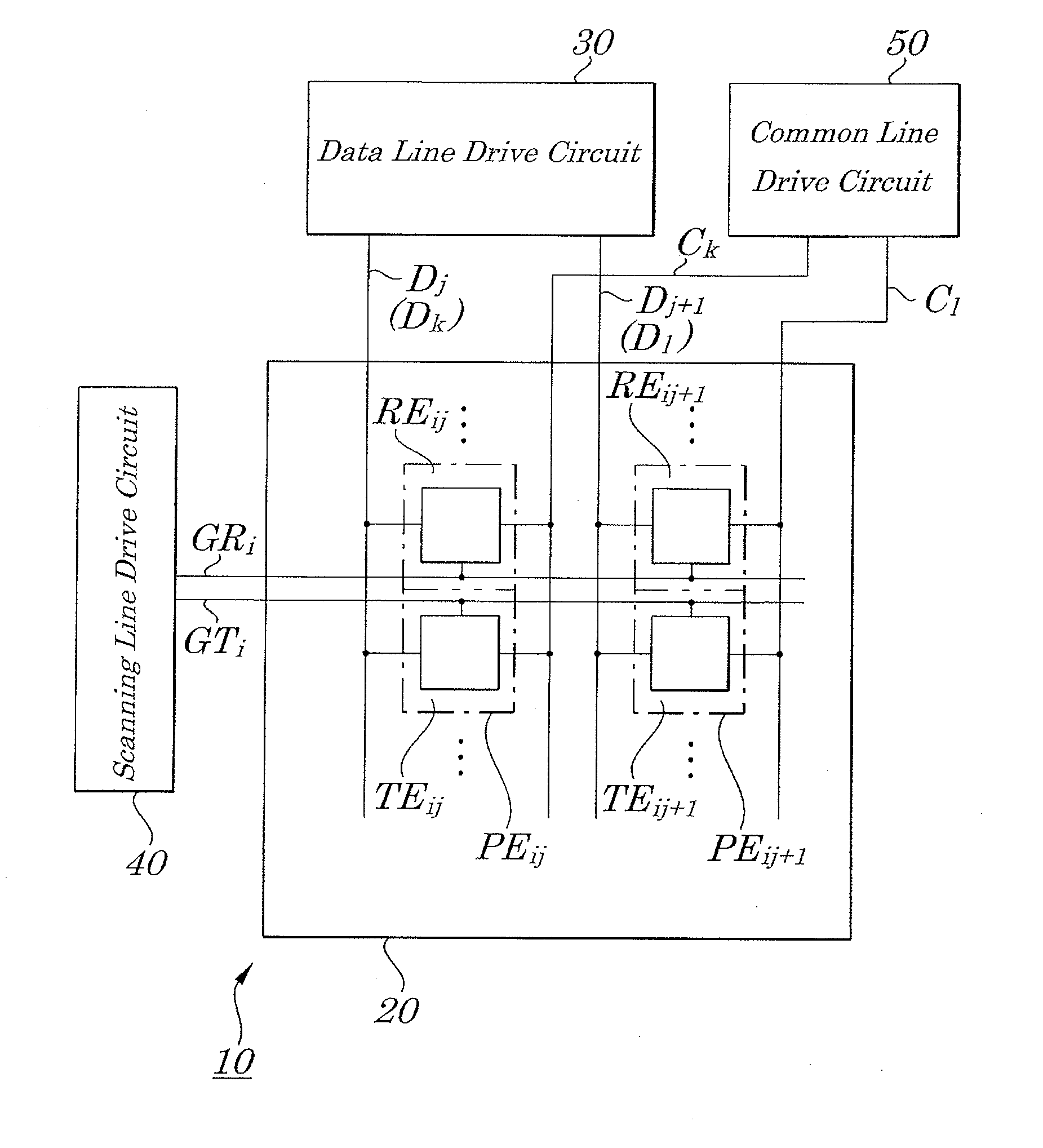
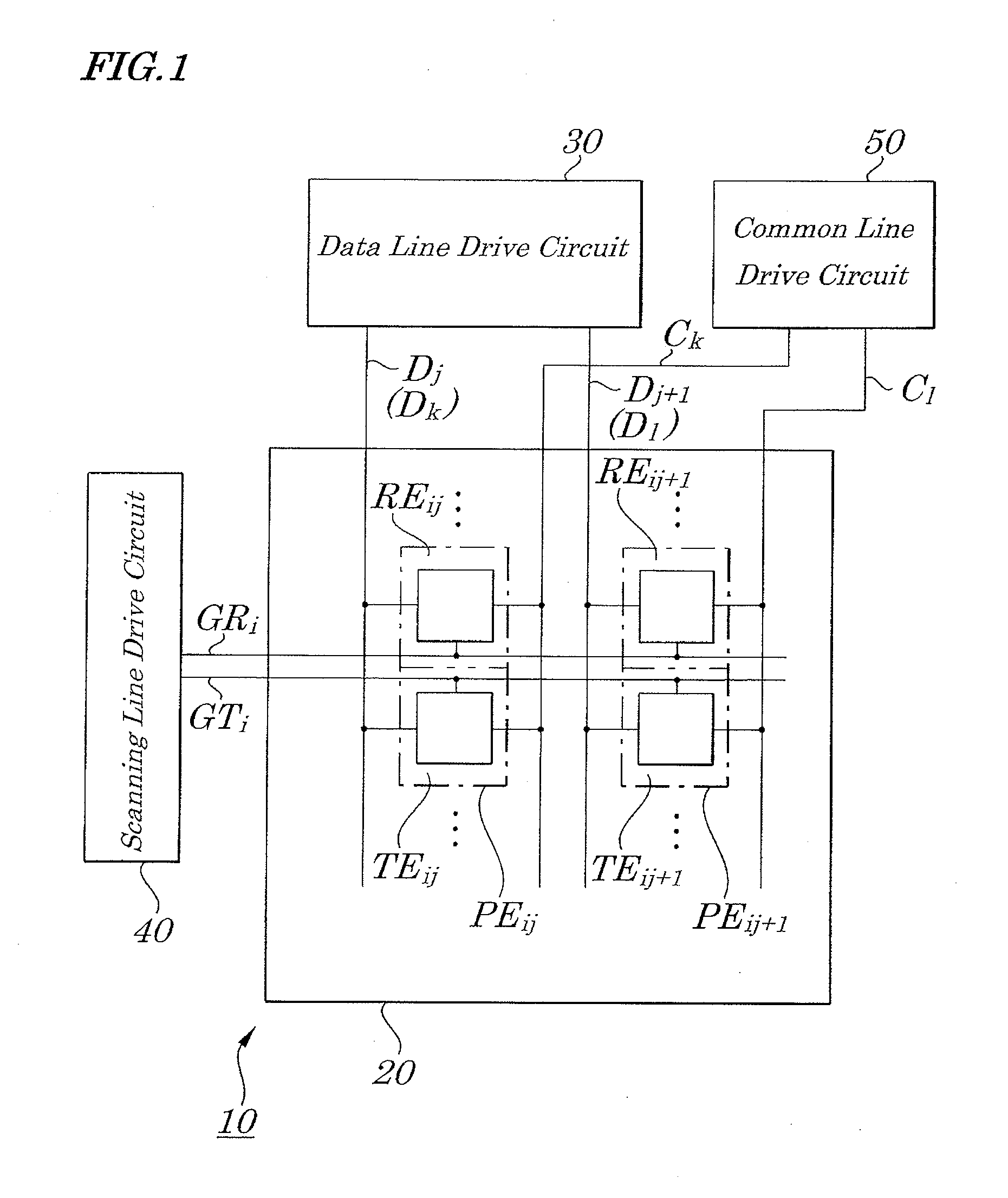
[0106]FIG. 8 is a block diagram for showing electrical configurations of a lateral field mode semi-transmissive liquid crystal display device (LCD) according to the second exemplary embodiment of the present invention, FIG. 9 is a plan view of a liquid crystal panel in the lateral field mode semi-transmissive LCD in which unit pixels are arranged in a form of a matrix array with two rows and two columns, FIG. 10 is a diagram for showing an equivalent circuit of the liquid crystal panel shown in FIG. 9, and FIG. 11 is a waveform chart of signals applied to electrodes and interconnections in a case where white display is provided on the lateral field mode semi-transmissive LCD.

[0107]The configurations of the present exemplary embodiment are different from those of the first exemplary embodiment in that common electrodes used for the unit pixels aligned in the odd-numbered column and common electrodes aligned in the even-numbered column are electrically combined with each other.

[0108]A...

third exemplary embodiment

[0129]According to a third exemplary embodiment of the present invention, there is provided a semi-transmissive liquid crystal display device including: a plurality of unit pixels arranged in a form of a matrix array, the unit pixels each including a transmissive region and a reflective region; a plurality of first scanning lines each connected to a first switching element formed in the transmissive region making up the unit pixel aligned in an odd-numbered column, and to a first switching element formed in the reflective region making up the unit pixel aligned in an even-numbered column; and a plurality of second scanning lines each connected to a second switching element formed in the transmissive region making up the unit pixel aligned in the even-numbered column, and to a second switching element formed in the reflective region making up the unit pixel aligned in the odd-numbered column, wherein the plurality of the first scanning lines, the plurality of the second scanning line...


PUM

PropertyMeasurementUnit
electrical potentialaaaaaaaaaa

Abstract

In a liquid crystal panel, a reflective pixel electrode and a transmissive pixel electrode in a unit pixel are supplied with an image signal output from a data line drive circuit, the two mutually different scanning signals output from a scanning line drive circuit, and common signals output from a common line drive circuit. The phase of the image signal is set different from that of the common signal. Further, a period during which the two scanning signals are selected is set in one horizontal period, the ending of the selection period for one of the scanning signals is set to a point in time before an electrical potential of the common signal changes, and the ending of the selection period for the other scanning signal is set to a point in time after the electrical potential of the common signal changes.

Description

INCORPORATION BY REFERENCE[0001]This application is based upon and claims the benefit of priority from Japanese Patent Application No. 2009-157349, filed on Jul. 1, 2009, the disclosure of which is incorporated herein in its entirely by reference.BACKGROUND OF THE INVENTION[0002]1. Field of the Invention[0003]The present invention relates to a semi-transmissive Liquid crystal display device (LCD) that can improve display performance further while inhibiting an increase in dissipation power.[0004]2. Description of the Related Art[0005]As an LCD that combines functions of a transmissive LCD and those of a reflective LCD, a semi-transmissive LCD is known which type has a transmissive region and a reflective region in each of pixels. The transmissive region transmits light from a backlight light source used as a display light source and so can give good display in a relatively dark environment such as an indoor or dark room. The reflective region has a reflector plate so that external l...

Claims


Application Information

Patent Timeline
Patent Type & Authority Applications(United States)
IPC IPC(8): G09G3/36G02F1/1343
CPCG02F1/134363G09G3/3614G09G3/3677G09G2300/0456G09G3/3655
Inventor MORI, KENICHISAKAMOTO, MICHIAKI
Owner NEC LCD TECH CORP
Why Eureka
Try Eureka