Reversible feed roller with radially extendible fingers

a feed roller and radial extension technology, which is applied in the direction of loaders, conveyers, mowers, etc., can solve the problems of blockage which cannot be released by machine operation and requires manual intervention of operators, so as to improve crop feeding

Active Publication Date: 2008-07-01
MACDON INDS
View PDF7 Cites 34 Cited by
  • Summary
  • Abstract
  • Description
  • Claims
  • Application Information

AI Technical Summary

Benefits of technology

[0014]It is one object of the invention to provide a reversible feed roller which is arranged to improve feeding of the crop in the reverse direction.
[0021]each finger having an inner end inside an interior of the roller and arranged to project outwardly from the interior of the roller through the peripheral surface to an outer end for engaging the crop material on the exterior of the roller for assisting in transferring the crop material from the supply location to the receiving location;
[0045]each finger having an inner end inside an interior of the roller and arranged to project outwardly from the interior of the roller through the peripheral surface to an outer end for engaging the crop material on the exterior of the roller for assisting in transferring the crop material from the supply location to the receiving location;
[0060]each finger having an inner end inside an interior of the roller and arranged to project outwardly from the interior of the roller through the peripheral surface to an outer end for engaging the crop material on the exterior of the roller for assisting in transferring the crop material from the supply location to the receiving location;

Problems solved by technology

One problem which arises with combine harvesters of this general type either using an auger type header or using a draper type header is that over feeding of the crop material into the feeder house can cause a blockage either at the entry to the feeder house or within the feeder house or even at the rotor of the combine harvester.
However in some cases there is a tendency for the crop material to collect in the area in front of the feed roller or to be back fed around the feed roller in a wrapping action.
If either of these events occurs, there is a significant risk that the material will become compressed in these areas leading to a blockage which cannot be released by operation of the machine and requires the manual intervention of the operator.

Method used


Image

  • Reversible feed roller with radially extendible fingers
  • Reversible feed roller with radially extendible fingers
  • Reversible feed roller with radially extendible fingers

Examples


Embodiment Construction

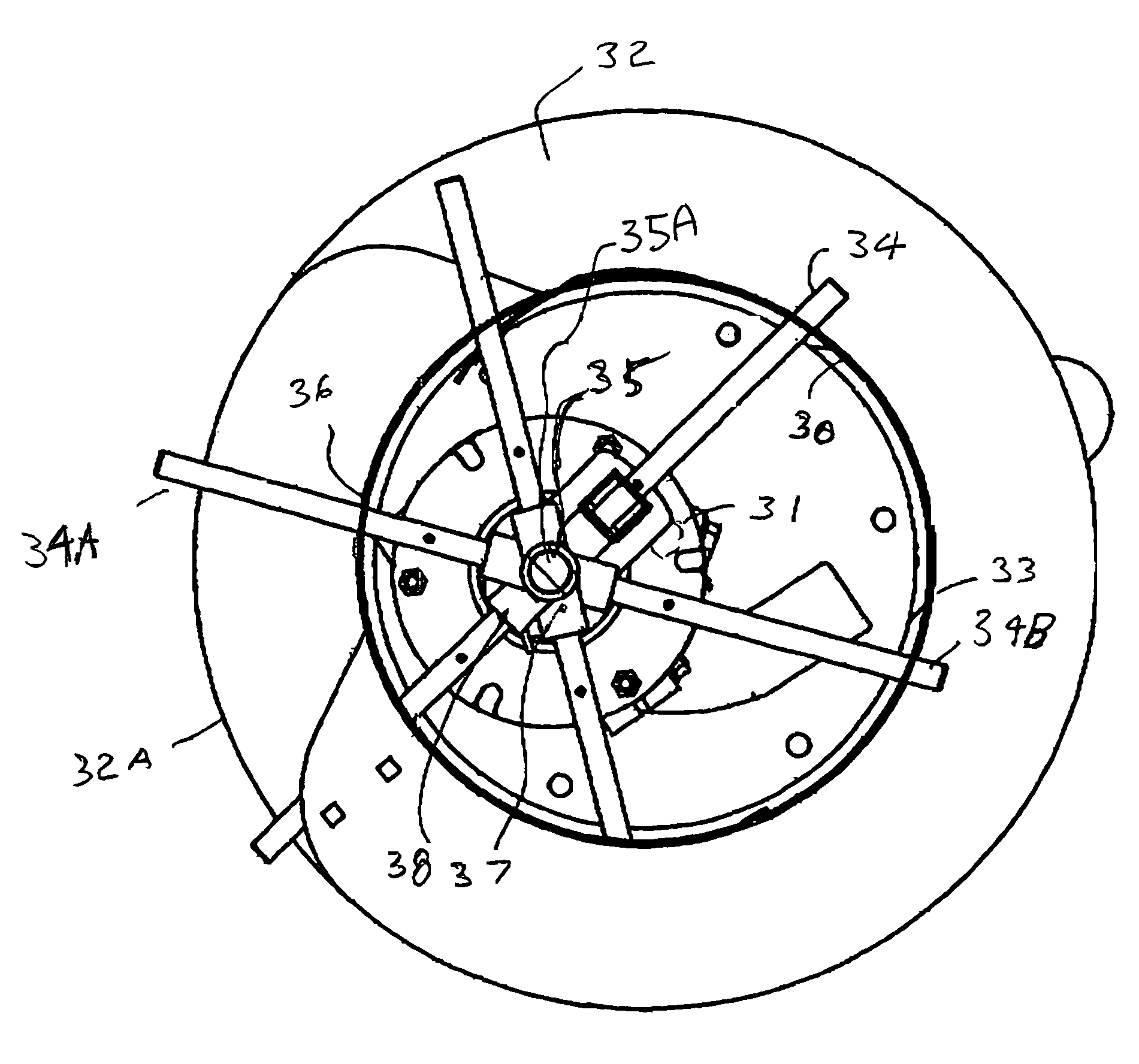
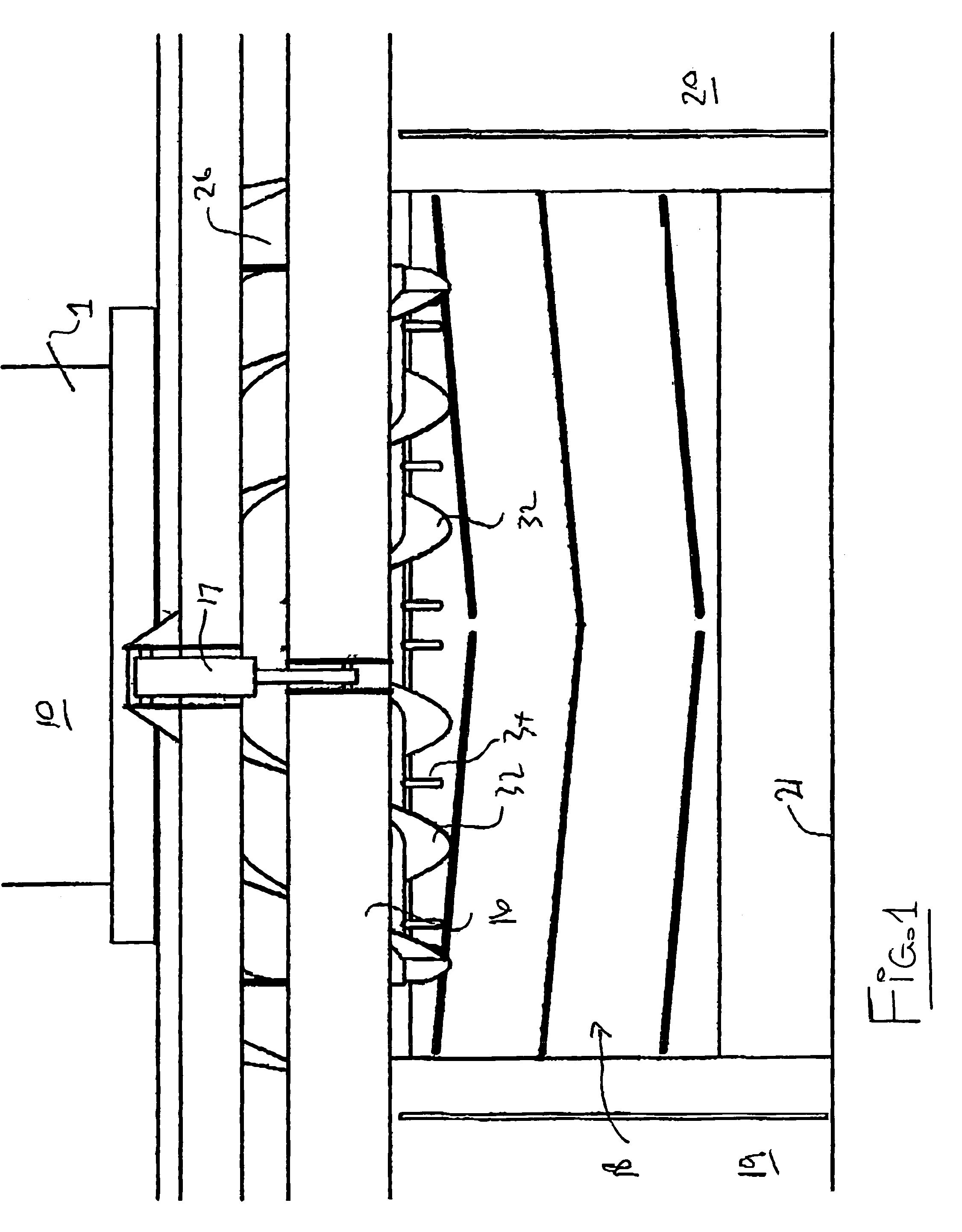
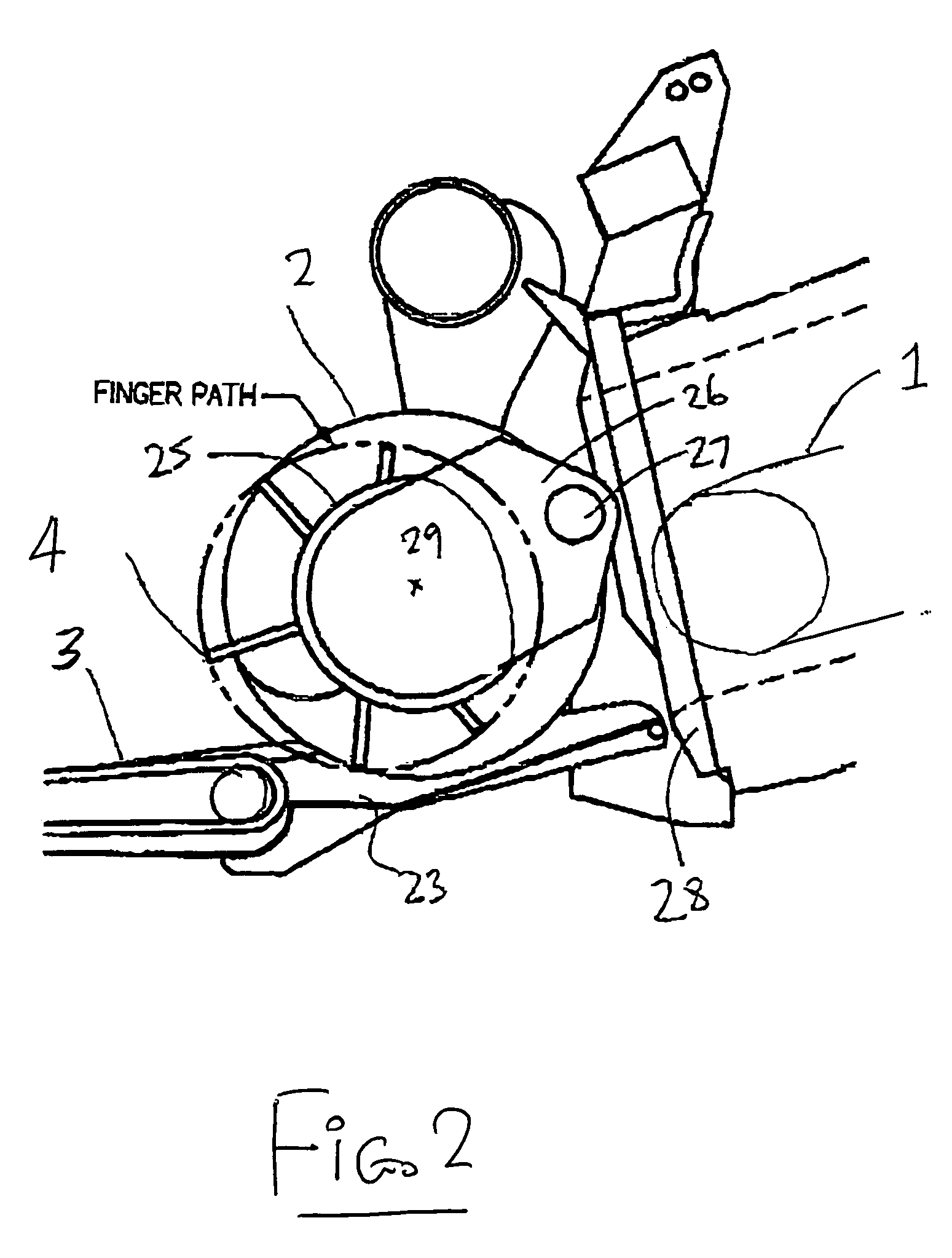
[0087]In FIGS. 1, 2 and 3 is shown an arrangement of header and feeder house for a combine harvester of the type generally shown in U.S. Pat. No. 6,675,568 issued Jan. 13th, 2004 of the present assignee and Canadian Published Application 2,341,283 published Sep. 16th, 2002, the disclosures of which is incorporated herein by reference.

[0088]Details of the main construction of the header are omitted since these are well known to one skilled in the art and are available from the above patent documents. The present arrangement is concerned primarily with the construction of the feed roller which is shown in detail herein so that other arrangements shown in the present documents may vary in accordance with the requirements of a person skilled in the art.

[0089]Thus the arrangement as shown comprises a feeder house 10 having a feeder chain 11 mounted within the feeder house for rotation of the feeder chain around a drive sprocket 12 so that crop material is carried underneath the bottom ru...


PUM


Abstract

A feed roller primarily for feeding crop into a feeder house of a combine harvester is located above and behind a feed draper and includes an outer flight and retractable fingers for feeding the crop through the zone behind the draper and into the feeder house. The fingers rotate about a finger axis offset from the roller axis so that they extend to a maximum at the draper and are retracted behind the roller to release the crop. When the roller is reversed to release a blockage, the fingers are also reversed in direction and the finger axis is moved rearwardly to the opposite side of the roller so that the fingers are extended behind the roller at the feeder house and retracted at the draper. This movement is done automatically on reversing the roller and uses power from the reversal to move the finger axis using a clutch. An anti-distortion wheel is mounted on the finger shaft to prevent retraction of the finger ends into the roller which can cause damage by loss of proper guidance.

Description

[0001]This application claims the benefit under 35 U.S.C. 119 of the filing date of Provisional Application No. 60 / 579,652 filed Jun. 16th, 2004.[0002]This invention relates to a reversible feed roller of the type having generally radially extending fingers which rotate about a finger axis offset from the roller axis so that their length extending from the roller surface changes around the roller axis for engaging into and for releasing the crop.BACKGROUND OF THE INVENTION[0003]Feed rollers are commonly used in crop harvesting machines for guiding the crop from a position in front of the roller to a position rearwardly of the roller. Such rollers are used in many different locations in crop feeding systems and the arrangement described herein is not limited to any particular location of such a crop feeding roller.[0004]However one primary use of such rollers is in that of guiding the crop from a harvesting header into the feeder house of a combine harvester. Such headers can be of t...

Claims


Application Information

Patent Timeline
Patent Type & Authority Patents(United States)
IPC IPC(8): A01D89/00A01D41/12A01D43/02A01D57/01A01D61/00
CPCA01D61/008A01D61/006
Inventor PATTERSON, ROGER L.
Owner MACDON INDS
Why Eureka
Try Eureka