Directional solidification furnace with improved crucible cover part

A technology of directional solidification furnace and crucible cover, which is applied in the direction of self-solidification, polycrystalline material growth, crystal growth, etc., to achieve the effects of ensuring pollution, reducing costs, and increasing feed materials

Inactive Publication Date: 2010-12-15
王楚雯
View PDF5 Cites 11 Cited by
  • Summary
  • Abstract
  • Description
  • Claims
  • Application Information

AI Technical Summary

Problems solved by technology

[0006] In view of this, it is necessary to provide a new directional solidification furnace, which can solve the positioning problem of the gas path in the existing directional

Method used


Image

  • Directional solidification furnace with improved crucible cover part
  • Directional solidification furnace with improved crucible cover part
  • Directional solidification furnace with improved crucible cover part

Examples


Embodiment Construction

[0032] Embodiments of the present invention are described in detail below, examples of which are shown in the drawings, wherein the same or similar reference numerals designate the same or similar elements or elements having the same or similar functions throughout. The embodiments described below by referring to the figures are exemplary only for explaining the present invention and should not be construed as limiting the present invention.

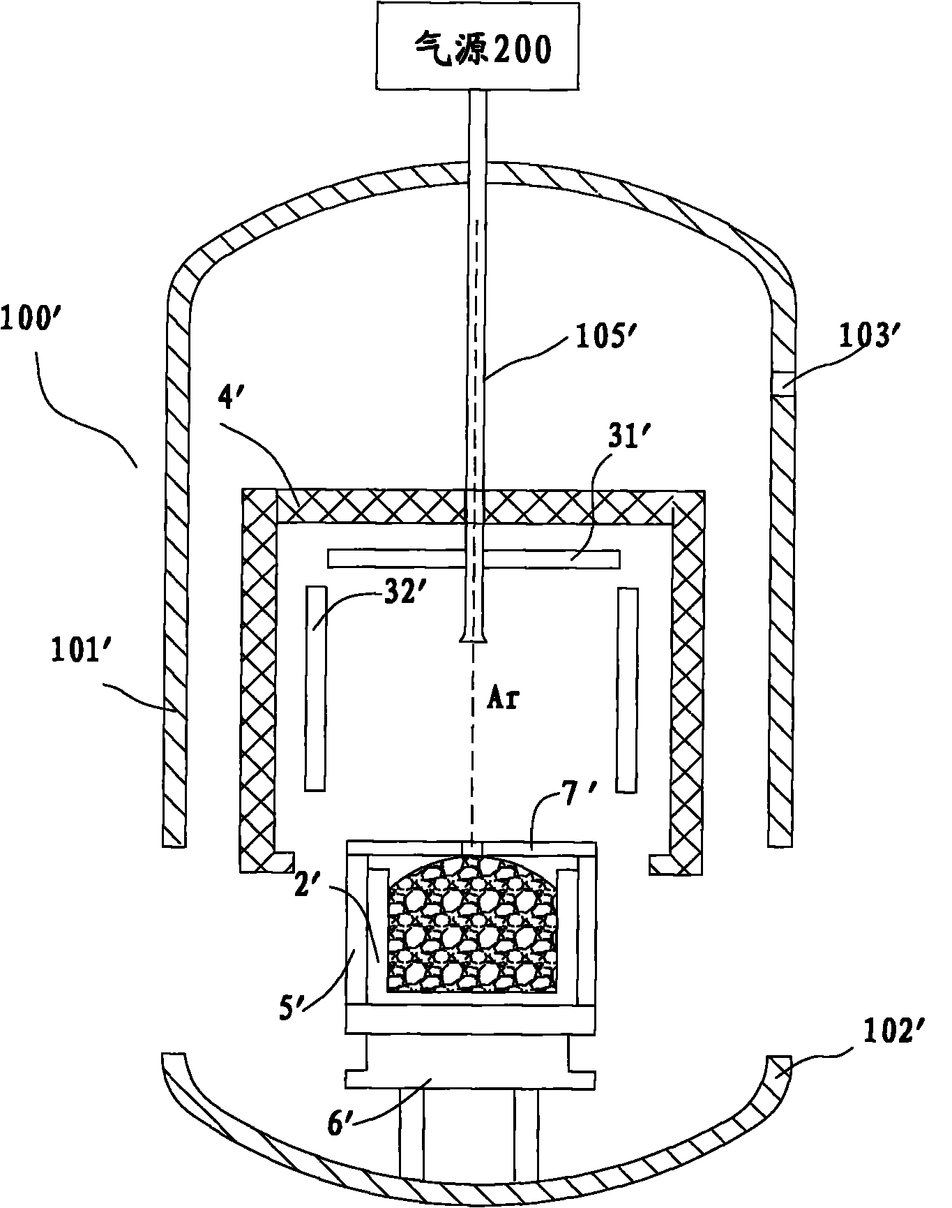
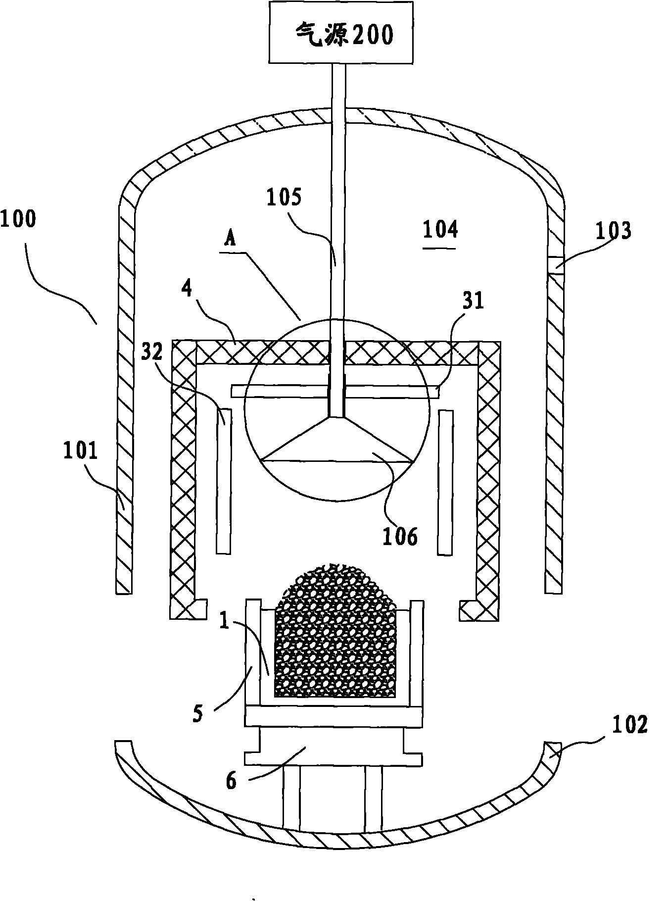
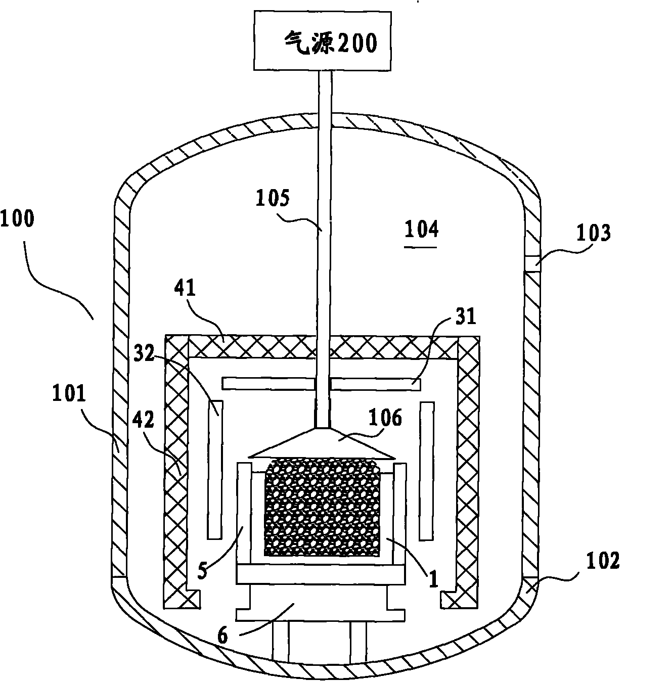
[0033] The present invention relates to a system or apparatus for growing polycrystalline material. The directional solidification furnace according to the present invention will be described below by taking the polycrystalline furnace for manufacturing polycrystalline as an example, wherein figure 2 It shows a schematic structural view of the directional solidification furnace 100 according to an embodiment of the present invention after the charging is completed and before the upper and lower furnace bodies are closed; image 3 A sch...


PUM


Abstract

The invention discloses a directional solidification furnace, which comprises an upper furnace body, a lower furnace body, a crucible, at least one heater, a crucible holder, a heat insulation component, a breather pipe and a crucible cover part, wherein the lower furnace body is matched with the upper furnace body to form a furnace body space; the crucible is arranged in the furnace body space and constructed to accommodate a feedstock; the at least one heater is used for heating the crucible and melting the feedstock accommodated in the crucible; the crucible holder is used for holding the crucible; the heat insulation component is constructed to longitudinally move relative to the crucible so as to control directional solidification of the feedstock in the crucible; the breather pipe is connected with an external gas source and vertically passes through the heat insulation component; and the crucible cover part is detachably arranged at the bottom of the breather pipe, and the sizeof the crucible cover part is adapted to the size of the top of the crucible so as to cover above the crucible. The directional solidification furnace can ensure that the furnace cavity is not polluted at the same time of realizing increment of the feedstock so as to improve the production efficiency and reduce the cost at the same time of ensuring the quality of a produced billet.

Description

technical field [0001] The present invention relates to production equipment such as monocrystalline or polycrystalline ingots, and more particularly to a directional solidification furnace with an improved crucible lid. Background technique [0002] In existing directional solidification equipment or systems for manufacturing polycrystalline ingots, since the raw materials used to produce polycrystalline ingots (such as polycrystalline silicon ingots, etc.) are block or granular, there are a large number of gaps between the blocks, resulting in the filling of quartz The crucible's solid polycrystalline feedstock is melted and shrinks considerably. However, it is expensive to manufacture polycrystalline ingots by using a directional solidification system, and the charging amount directly determines the production efficiency and cost, so it is necessary to take technical measures to increase the feeding amount. In order to realize multi-charging, it can be considered that wh...

Claims


Application Information

Patent Timeline
IPC IPC(8): C30B11/00C30B28/06C30B29/06
Inventor 李园
Owner 王楚雯
Why Eureka
Try Eureka