Rotary vane pump

a rotary vane pump and rotary vane technology, which is applied in the direction of rotary/oscillating piston pump components, machines/engines, liquid fuel engines, etc., can solve the problems of inefficiency, and inefficiency of previously developed rotary vane pumps

Inactive Publication Date: 2008-07-01
TUTHILL CORP
View PDF9 Cites 3 Cited by
  • Summary
  • Abstract
  • Description
  • Claims
  • Application Information

AI Technical Summary

Problems solved by technology

Although effective, previously developed rotary vane pumps are not without their problems.
For instance, previously developed rotary vane pumps are inefficient.
One reason for their inefficiency is the utilization of dynamic seals to seal in the fluid being pumped.
This dynamic seal results in friction losses and is prone to leakage and failure.
Conventional vanes are also inefficiently designed.
Such conventional vane designs result in high shear forces and accompanying friction losses as a relatively large surface area of a side of a vane slides against a wall of the slot in which the vane reciprocates radially inward and outward as an outer edge of the vane slides along the sealing surface of the pump housing.
Additionally, previously developed rotary vane pumps which do not use mechanical means to bias the vanes outward to the sealing surface, i.e., which use centrifugal and hydraulic forces to bias the vanes outward, have a vane design or geometry that does not provide adequate hydraulic balancing of the forces exerted upon the vane to drive the vane toward the sealing surface, such that the vane is either overly or under driven outward toward the sealing surface by the hydraulic forces acting upon the vane.
Other problems arise from conventional rotor and drive shaft combinations.
For example, the rotor and drive shaft combination of previously developed rotary vane pumps are expensive to manufacture since the rotor and drive shaft are separately machined, and then coupled to one another.
In addition, previously developed rotary vane pumps have not been able to be manufactured in miniature sizes for use in low flow situations.
Additionally, previously developed rotor designs have not been able to address the issue of providing rigidity between the dividing members (the material between adjacent slots in which the vanes reciprocate) of the rotor, especially in smaller diameter rotors.

Method used


Image

  • Rotary vane pump
  • Rotary vane pump
  • Rotary vane pump

Examples


Embodiment Construction

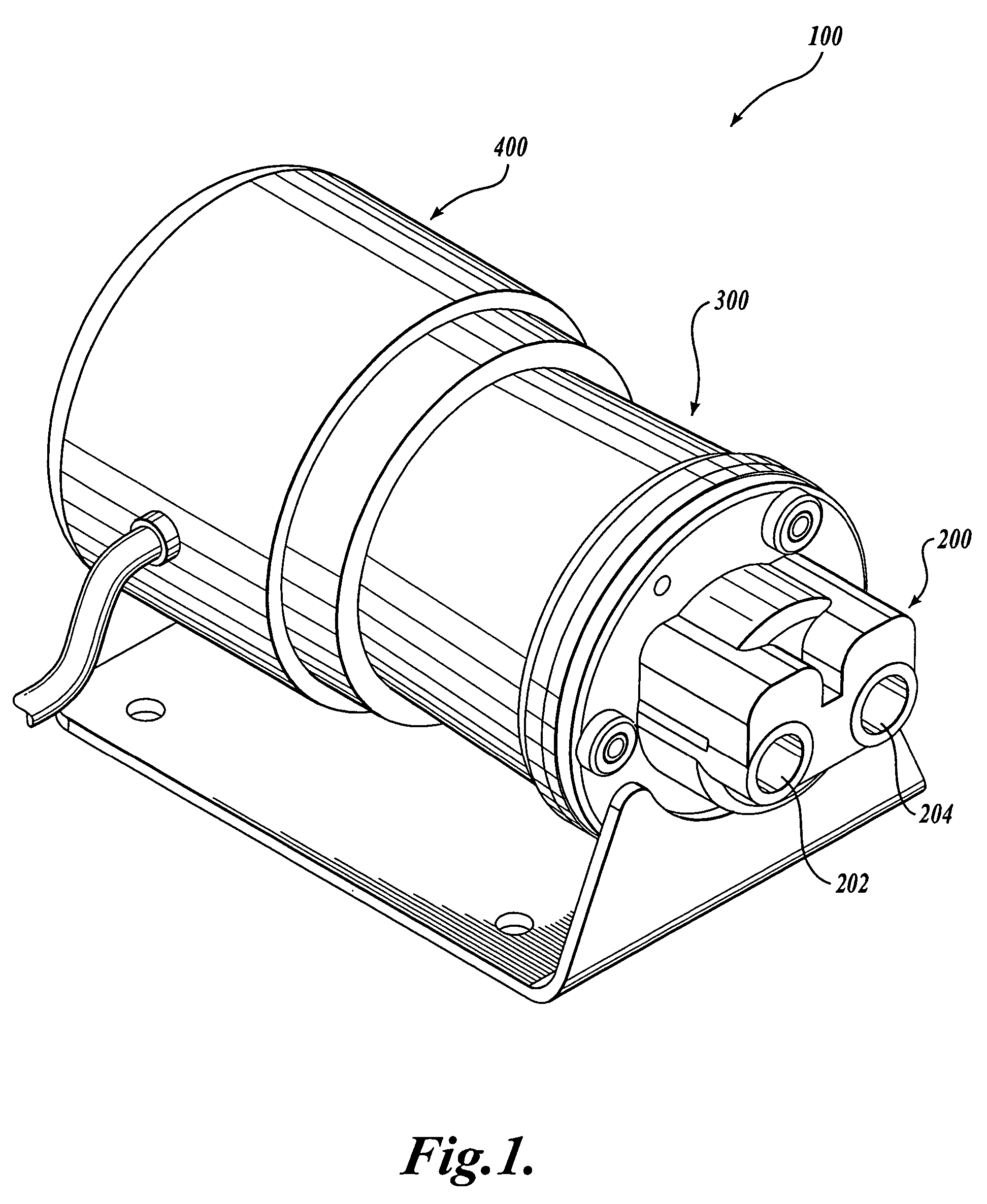
[0028]Referring to FIGS. 1-11, one embodiment of a pump assembly 100 formed in accordance with the present invention for pumping a fluid is shown. Turning to FIG. 1, the pump assembly 100 includes a rotary vane pump 200 coupled to a prime mover 400 via a transmission, such as magnetic coupling unit 300. Generally described, the prime mover 400 provides a rotary input to the magnetic coupling unit 300. The magnetic coupling unit 300 transfers the rotary input from the prime mover 400 to the rotary vane pump 200. The rotary vane pump 200, using the energy transferred to it from the prime mover 400 via the magnetic coupling unit 300, pumps a fluid from an input passageway 202 to an outlet passageway 204.

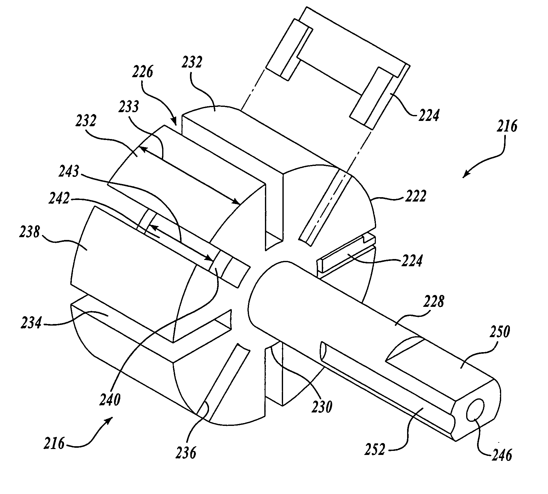
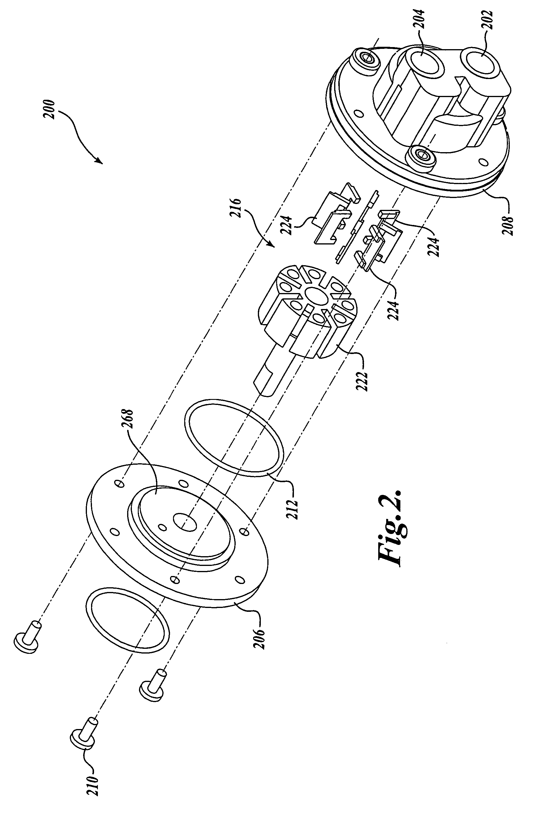
[0029]Focusing now in more detail upon the rotary vane pump 200 and referring to FIG. 2, the rotary vane pump 200 includes a two piece housing formed from an end plate 206 and a main body portion 208. The end plate 206 may be coupled to the main body portion 208 by any suitable means, o...


PUM

PropertyMeasurementUnit
diameteraaaaaaaaaa
diameteraaaaaaaaaa
diameteraaaaaaaaaa

Abstract

A rotary vane pump (200) for pumping a fluid. The rotary vane pump includes a pump housing (206 and 208) and a rotor having a plurality of dividing members (232) and a plurality of slots (226) disposed between adjacent dividing members. The rotary vane pump also includes a plurality of strengthening members (240), each strengthening member disposed in one of the plurality of slots and coupled to adjacent dividing members. The rotary vane pump also includes a plurality of vanes (224), each vane moveably disposed in one of the plurality of slots.

Description

CROSS-REFERENCE TO RELATED APPLICATION[0001]This application claims the benefit of U.S. Provisional Application No. 60 / 556,279, filed Mar. 25, 2004, entitled Vane Pump, the disclosure of which is hereby expressly incorporated by reference.FIELD OF THE INVENTION[0002]The present invention relates generally to pumps for pumping fluids, and more specifically to rotary vane pumps.BACKGROUND OF THE INVENTION[0003]Rotary vane pumps are positive displacement pumps that utilize vanes that work with a cam or sealing surface to draw fluid into and force said fluid out of a pump housing. Although effective, previously developed rotary vane pumps are not without their problems. For instance, previously developed rotary vane pumps are inefficient. One reason for their inefficiency is the utilization of dynamic seals to seal in the fluid being pumped. As a case in point, previously developed rotary vane pumps use a dynamic seal between a rotating input shaft coupled to a rotor and the pump housin...

Claims


Application Information

Patent Timeline
Patent Type & Authority Patents(United States)
IPC IPC(8): F03C2/00F04C18/00F01C1/00F01C19/00F01C21/08F03C4/00F04C2/00F04C2/344F04C15/00F04C27/00F16N13/20H02K5/128H02K7/14
CPCF01C21/08F01C21/0809F01C21/0863F04C2/3441H02K7/14F04C15/0069H02K5/128F04C2/3442F05C2225/00F05C2225/12
Inventor WOOD, GREGORY PCORTEZ, PHILLIP VCITRO, MICHAEL A
Owner TUTHILL CORP
Why Eureka
Try Eureka