
Fin assembly

a technology of fins and parts, applied in the field of fins, can solve the problems of reducing manoeuvrability, increasing drag, and unable to achieve significant commercial success or acceptance in the surfing community

Inactive Publication Date: 2008-07-01
C & C FIN DESIGNS
View PDF18 Cites 10 Cited by
  • Summary
  • Abstract
  • Description
  • Claims
  • Application Information

AI Technical Summary

Benefits of technology

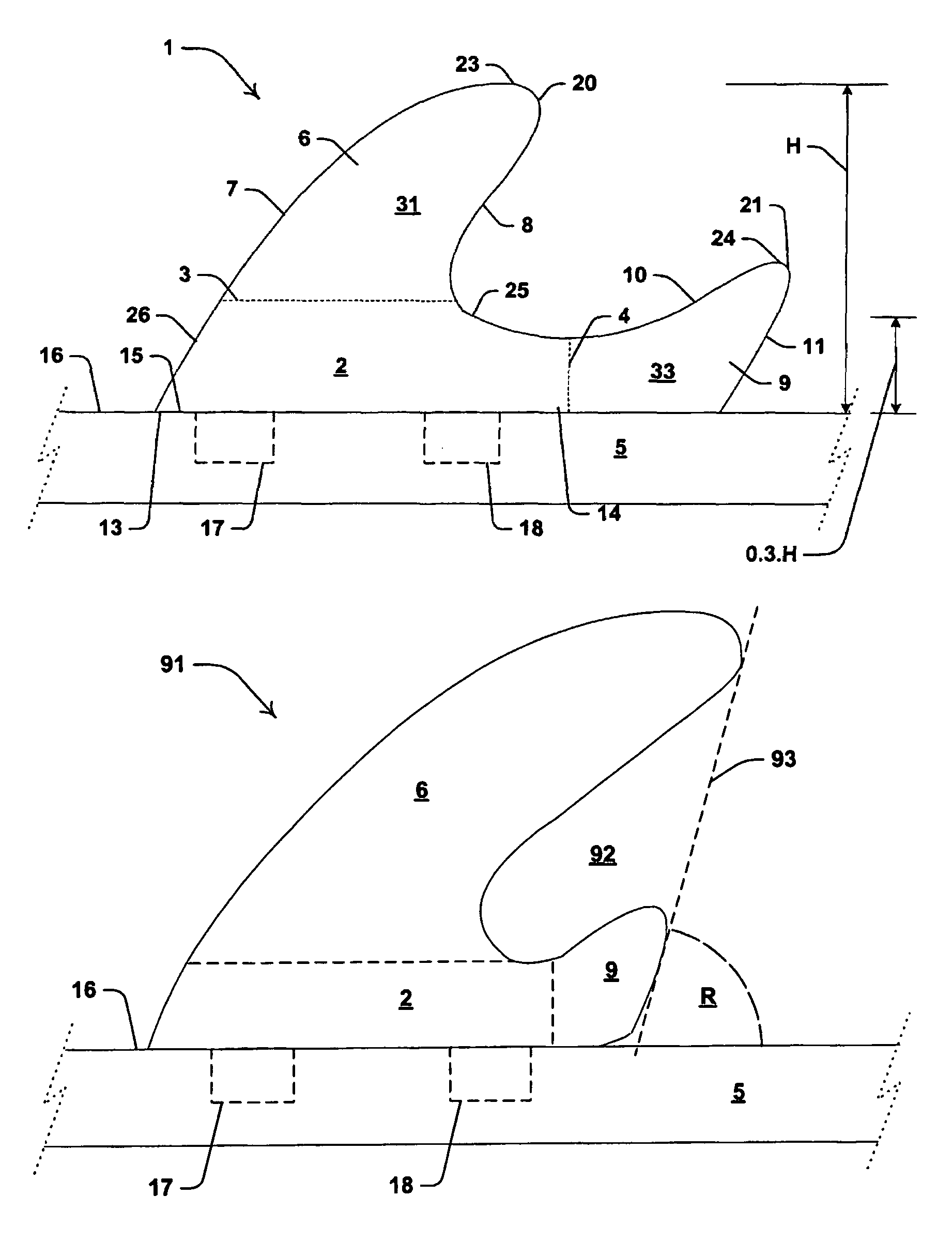
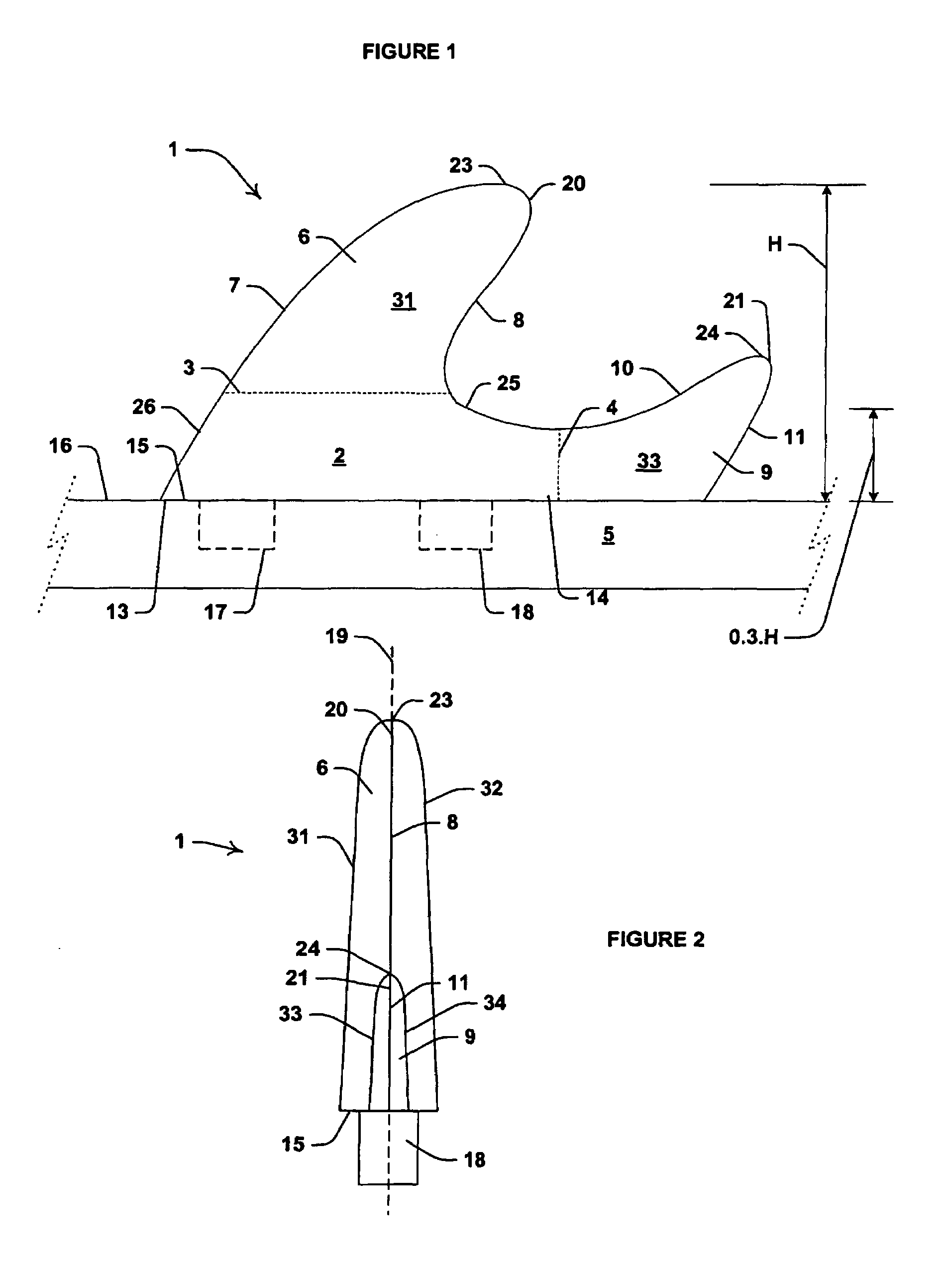
"The present invention provides a fin assembly for a surf craft that includes a base, a primary fin, and a secondary fin. The fins are integrally formed with the base and have leading and trailing edges that meet at a tip. The fins can be aligned or transversely spaced apart. The assembly also includes a feathered portion between the primary and secondary fins, which has a sectional area that is greater than the sectional area of the primary and secondary fins. The invention provides a more efficient and effective fin assembly for surf craft that improves performance and flexibility."

Problems solved by technology

While the triple fin arrangement has significant advantages over the Malabo fin, it also has substantial limitations, such as increased drag and reduced manoeuvrability.
However, as presently understood, it has enjoyed neither significant commercial success nor acceptance within the surfing community.
It is understood that this is a result of replacement fins needing to be received within the same retaining formations as the original fins, and also due to the limitations imposed by the highly image conscious nature of the users of the surfboards.

Method used


Image

  • Fin assembly
  • Fin assembly
  • Fin assembly

Examples


second embodiment

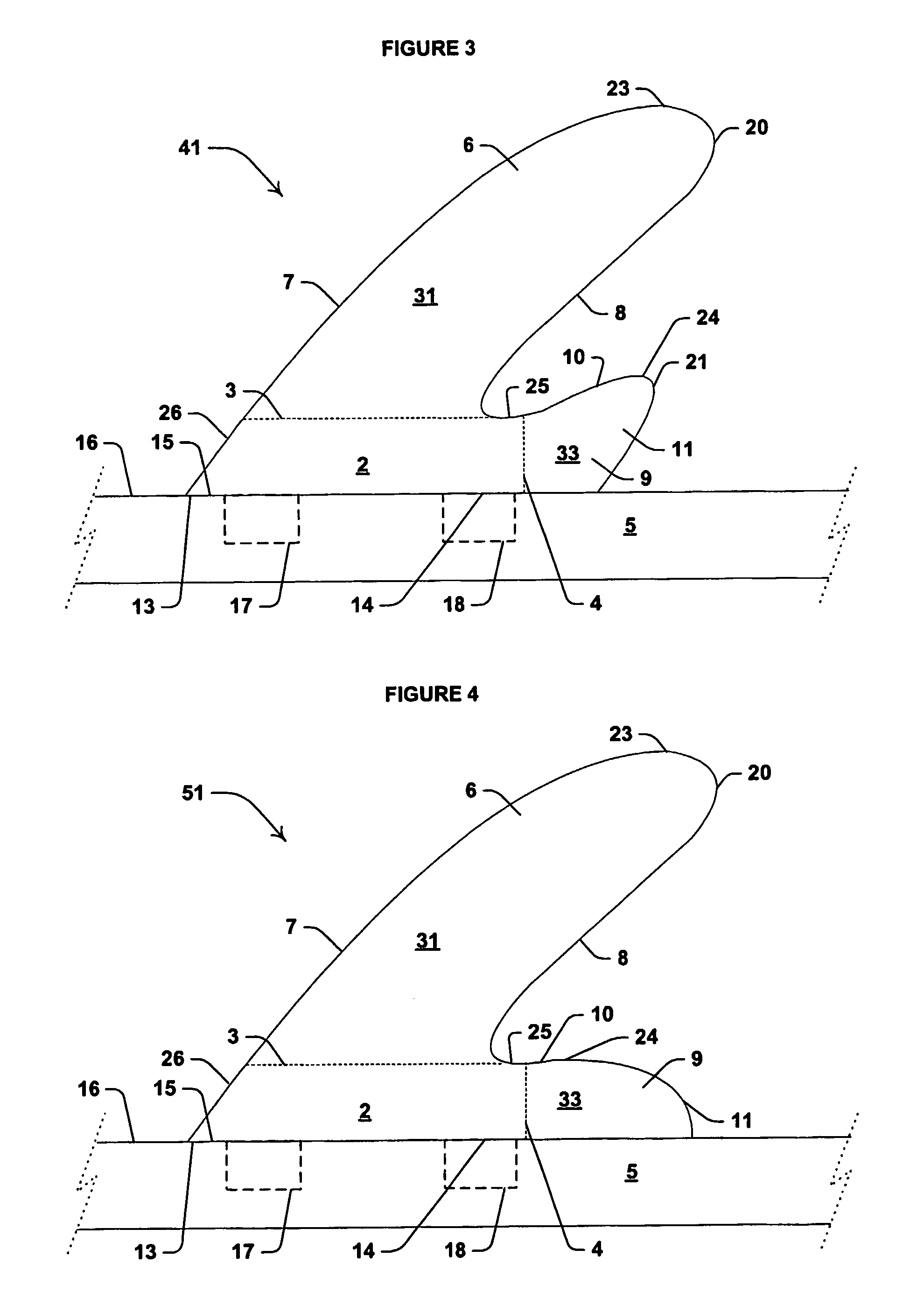
[0110]the invention, in the form of a fin assembly 41, is illustrated in FIG. 3, where corresponding features are denoted by corresponding reference numerals. Assembly 41 is not as longitudinally elongate as assembly 1, and intermediate edge 25 is very short. For comparison purposed, some key dimensions of assembly 41 are provided in Table 1.

[0111]Relative to assembly 1, assembly 41 has a greater depth, a smaller length adjacent to surface 16, a smaller sectional area A, and a lower percentage of the total area in the 0.3.H zone. The difference in performance between assembly 1 and assembly 41 is that the latter is even more maneuverable than the former, in that is will turn with less force being exerted by the surfer (or turn more when exposed to the same force).

third embodiment

[0112]the invention, in the form of a fin assembly 51, is illustrated in FIG. 4, where corresponding features are denoted by corresponding reference numerals. Assembly 51 is not as elongate as assembly 1, but more elongate than assembly 41. The key dimensions of assembly 51 are provided in Table 1 for ease of comparison with the prior art and the other embodiments of the invention.

[0113]While the 0.3.H area and the longitudinal length of fin assembly 51 adjacent to surface 16 are greater than for assembly 41, the peripheral edge and the sectional area of assembly 51 are both less than the corresponding dimensions for assembly 41. Moreover, 36% the sectional area of assembly 51 is in the bottom 22% of the height of fin 6. That is, the 0.22.H area is 36%.

[0114]The effect of this on the performance of assembly 51 is far smoother in use, in that it offers a more progressive feel to the surfer over assemblies 1 and 41. The trade off is slightly less “initial bite” when entering turns. Wh...


PUM

PropertyMeasurementUnit
areaaaaaaaaaaa
areaaaaaaaaaaa
perimeteraaaaaaaaaa

Abstract

An integrally formed fibreglass fin assembly (1) including a base (2)—that is defined by broken lines (3,4)—for mounting the assembly to an object in the form of a surfboard (5). A primary fin (6) extends upwardly from base (2)—in that it extends upwardly from line (3)—and has a compound arcuate leading primary edge (7) and a compound arcuate trailing primary edge (8). A secondary fin (9) extends rearwardly and upwardly from base (2)—in that it extends from line (4)—and has a compound arcuate leading secondary edge (10) and a compound arcuate trailing secondary edge (11).

Description

CROSS REFERENCE TO RELATED APPLICATIONS[0001]This application is a National Stage of International Application No. PCT / AU03 / 00023, filed Jan. 14, 2003.BACKGROUND TO THE INVENTION[0002]The present invention relates to a fin and in particular to a fin assembly.[0003]The invention has been developed primarily for use with surf craft such as surfboards and will be described hereinafter with reference to that application. However, the invention is not limited to that particular field of use and is also applicable to other surf craft including surf skis and bogie boards and to water craft including kayaks, canoes, boats, sailboards and the like.DISCUSSION OF THE PRIOR ART[0004]Known fins or fin assemblies for surfboards have only incrementally advanced in the last forty years notwithstanding the reduction in size of boards and the use of modern manufacturing materials and techniques. An early style fin has been used with a board known as the Malabo board, while more recent boards typicall...

Claims


Application Information

Patent Timeline
Patent Type & Authority Patents(United States)
IPC IPC(8): B63B1/00B63B3/38B63B35/79
CPCB63B35/7926B63B2231/52B63B32/62B63B32/66
Inventor CLUTTON, TROYCOLE, DEAN
Owner C & C FIN DESIGNS
Learn More