Arithmetic logic unit

Inactive Publication Date: 2008-07-01
ALTERA CORP
View PDF6 Cites 50 Cited by
  • Summary
  • Abstract
  • Description
  • Claims
  • Application Information

AI Technical Summary

Benefits of technology

[0011]It is an object of this invention to provide ALU circuitry in the form of a unified circuit th

Problems solved by technology

One drawback of the circuit in FIG. 1 is that ALU units are each formed as separate individual units and, therefore, require substantial die space additional routing resources—i.e., interconnect, wiring, etc.—and individualized logic.
Furthermore,

Method used


Image

  • Arithmetic logic unit
  • Arithmetic logic unit
  • Arithmetic logic unit

Examples


Embodiment Construction

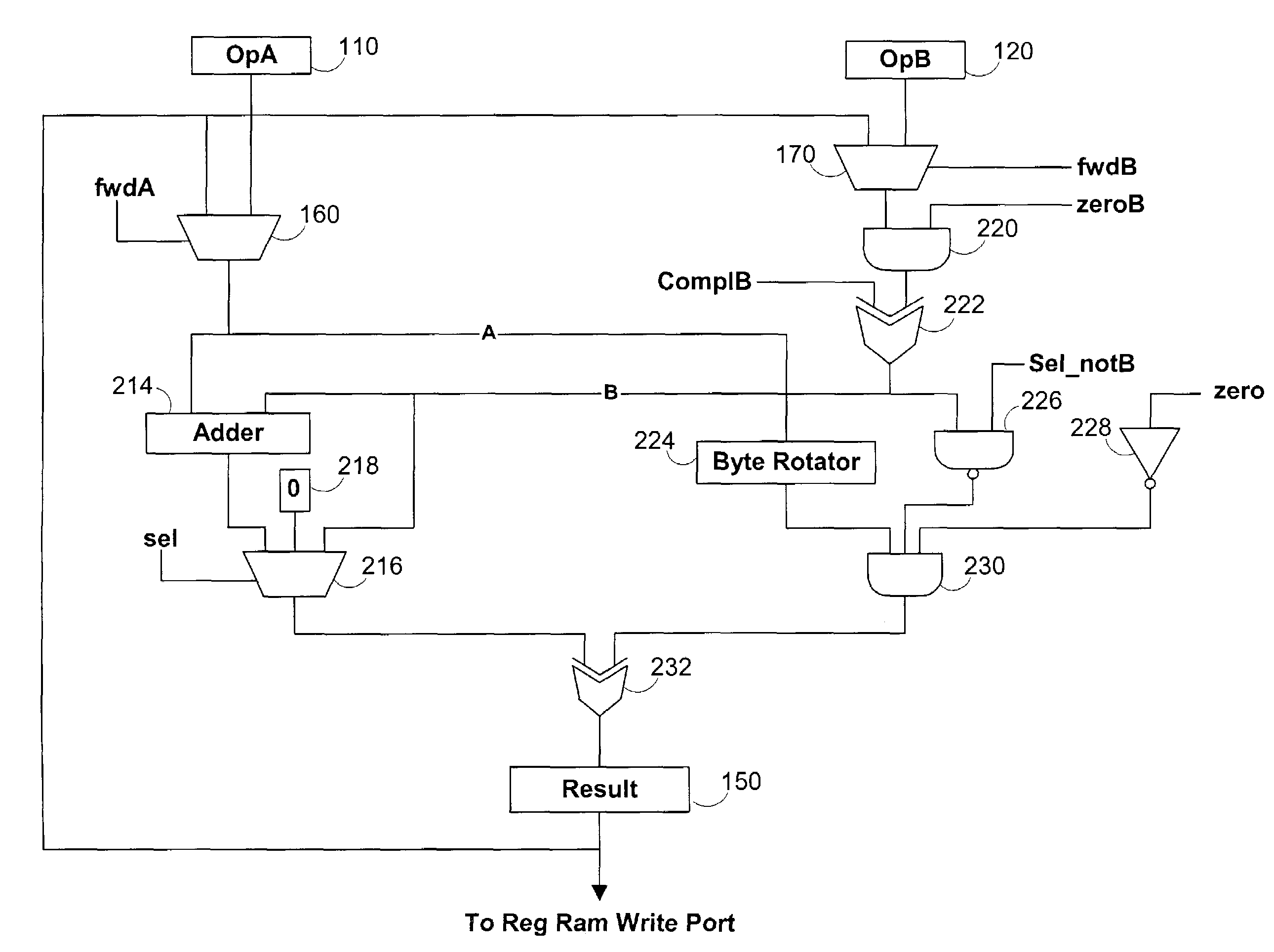
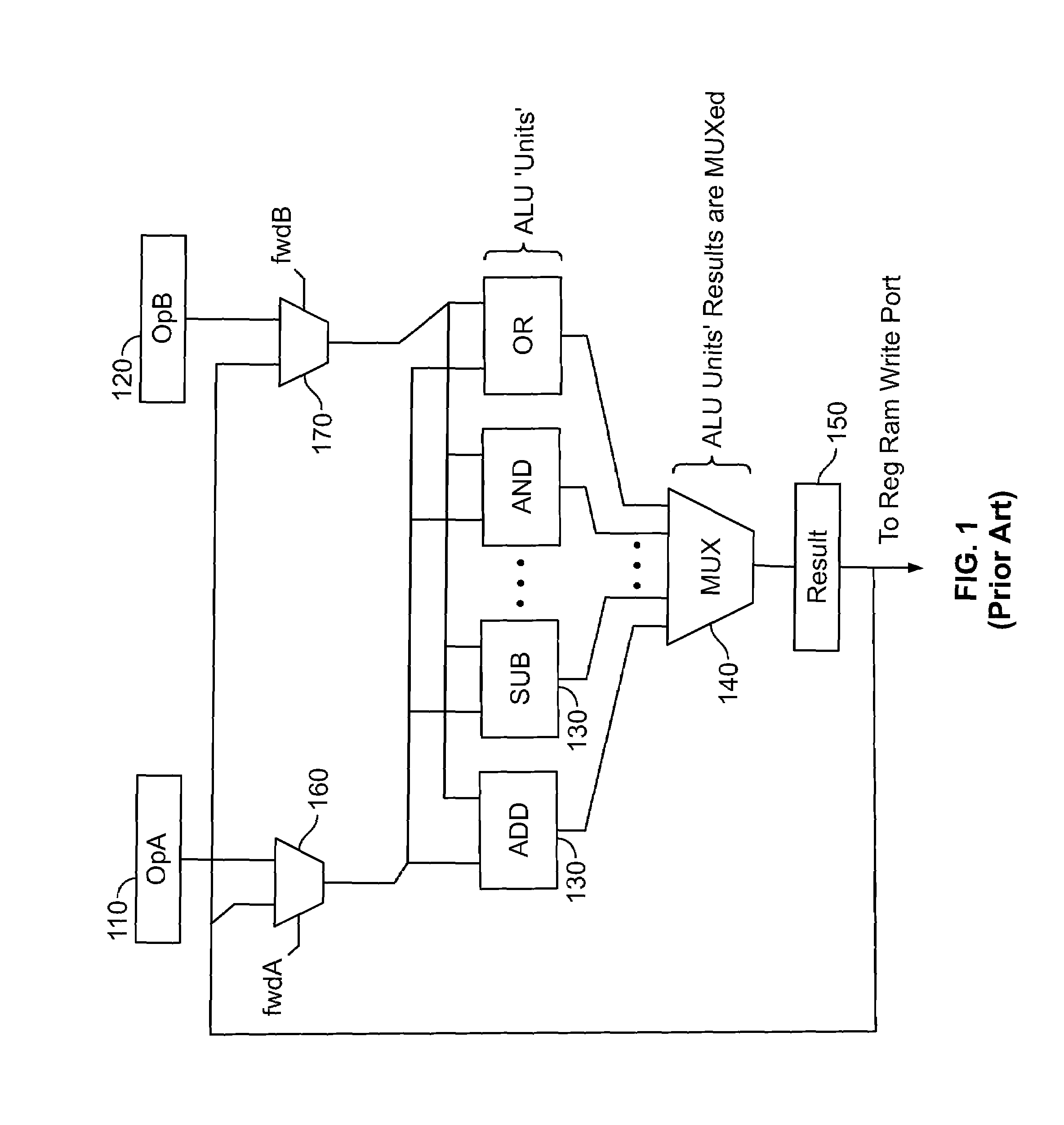
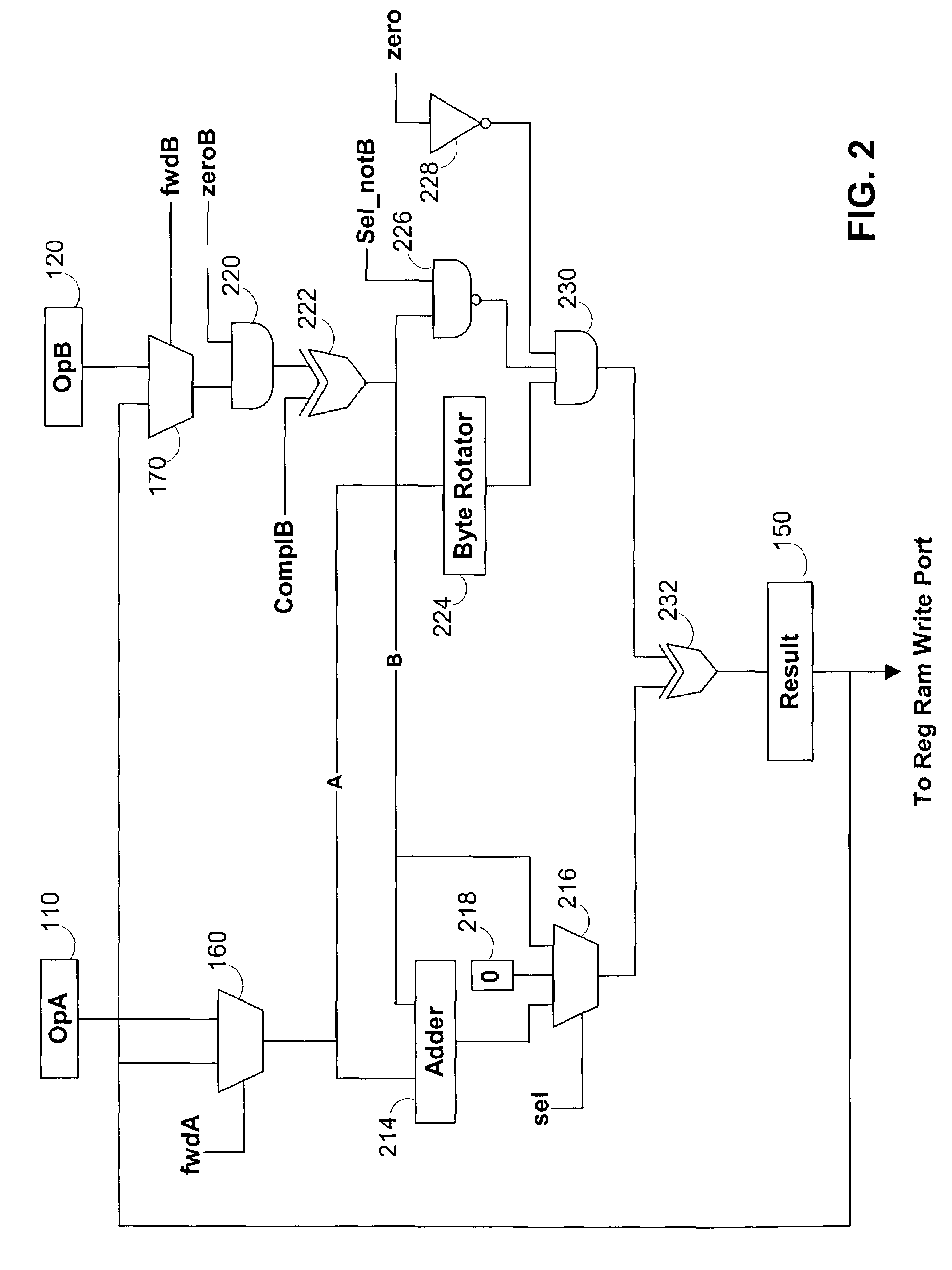
[0040]ALU circuitry according to the invention is provided. The ALU circuitry according to the invention preferably includes fewer logic gates and logic modules than are required by the conventional ALU circuitry. Furthermore, ALU circuitry according to the invention, may include only a single MUX (which may be implemented in a four-input LUT and which is typically propagated to and from using interconnect that is not non-nearest neighbor interconnect (see definition below)) between the register that provides the operand to the ALU and the result register at the output of the ALU. This configuration obtains a substantial reduction in routing delays than is available in the prior art. Because routing delays are significant sources of delay in ALUs in particular and in all devices which utilize ALUs generally, such as PLDs, an ALU according to the invention is significantly faster than a conventional ALU.

[0041]It should be noted that there are generally two types of routing delays in ...


PUM


Abstract

An arithmetic logic unit is provided. The arithmetic logic unit preferably includes a minimum of routing delays. An arithmetic logic unit according to the invention preferably receives a plurality of operands from a plurality of operand registers, performs an arithmetic operation on the operands, obtains a result of the arithmetic operation and that transmits the result to a result register. The arithmetic logic unit includes a signal propagation path that includes no greater than two routing paths that connect non-immediately adjacent logic elements.

Description

BACKGROUND OF THE INVENTION[0001]This invention relates to arithmetic logic unit (“ALU”) circuitry.[0002]ALU circuitry is used in microprocessors. Microprocessors process instructions in several stages. Typically microprocessors fetch—i.e., retrieve—an instruction, decode the instruction, read the operands upon which the instruction will be performed, execute an operation on the operands, and writeback the results of the operation to a suitable output such as a Random Access Memory via a Register Ram Write Port, a register bank or any other suitable location. The ALU circuitry typically forms a portion of, and is used in, the execute state of the microprocessor.[0003]Generally, microprocessors are “pipelined.”“Pipelining” refers to the fact that each of the processes of the microprocessor's stages may be occurring substantially simultaneously on different instructions. Thus, as the current instruction is being executed, a second instruction in the pipeline is being decoded and a thi...

Claims


Application Information

Patent Timeline
IPC IPC(8): G06F7/38
CPCG06F7/57
Inventor METZGEN, PAUL J.
Owner ALTERA CORP
Why Eureka
Try Eureka