Methods and arrangements in an access system

a technology of access system and access system, applied in data switching networks, frequency-division multiplexes, instruments, etc., to achieve the effect of simplifying switching, reducing internal resource usage and network bandwidth, and being efficient and comparatively simpl

Inactive Publication Date: 2005-07-14
TELEFON AB LM ERICSSON (PUBL)
View PDF5 Cites 20 Cited by
  • Summary
  • Abstract
  • Description
  • Claims
  • Application Information

AI Technical Summary

Benefits of technology

[0017] Still a problem is how to express the path between the source and destination allowing network equipment to minimize internal resource usage and network bandwidth, i.e. there should be no unnecessary frame duplication (flooding) in the network.
[0029] Yet an advantage is that simplified switching can be implemented within the reach of a large scale Public Access network based on Ethernet technology. The invention encompasses switching support for both wired and wireless connections between user devices and terminal points of an access network.

Problems solved by technology

Another problem is how to make the switching efficient in both directions between two communicating parts.
Still a problem is how to express the path between the source and destination allowing network equipment to minimize internal resource usage and network bandwidth, i.e. there should be no unnecessary frame duplication (flooding) in the network.
Yet a problem is how to implement support for simplified switching, within the reach of a large scale Public Access network based on Ethernet technology.

Method used


Image

  • Methods and arrangements in an access system
  • Methods and arrangements in an access system
  • Methods and arrangements in an access system

Examples


Embodiment Construction

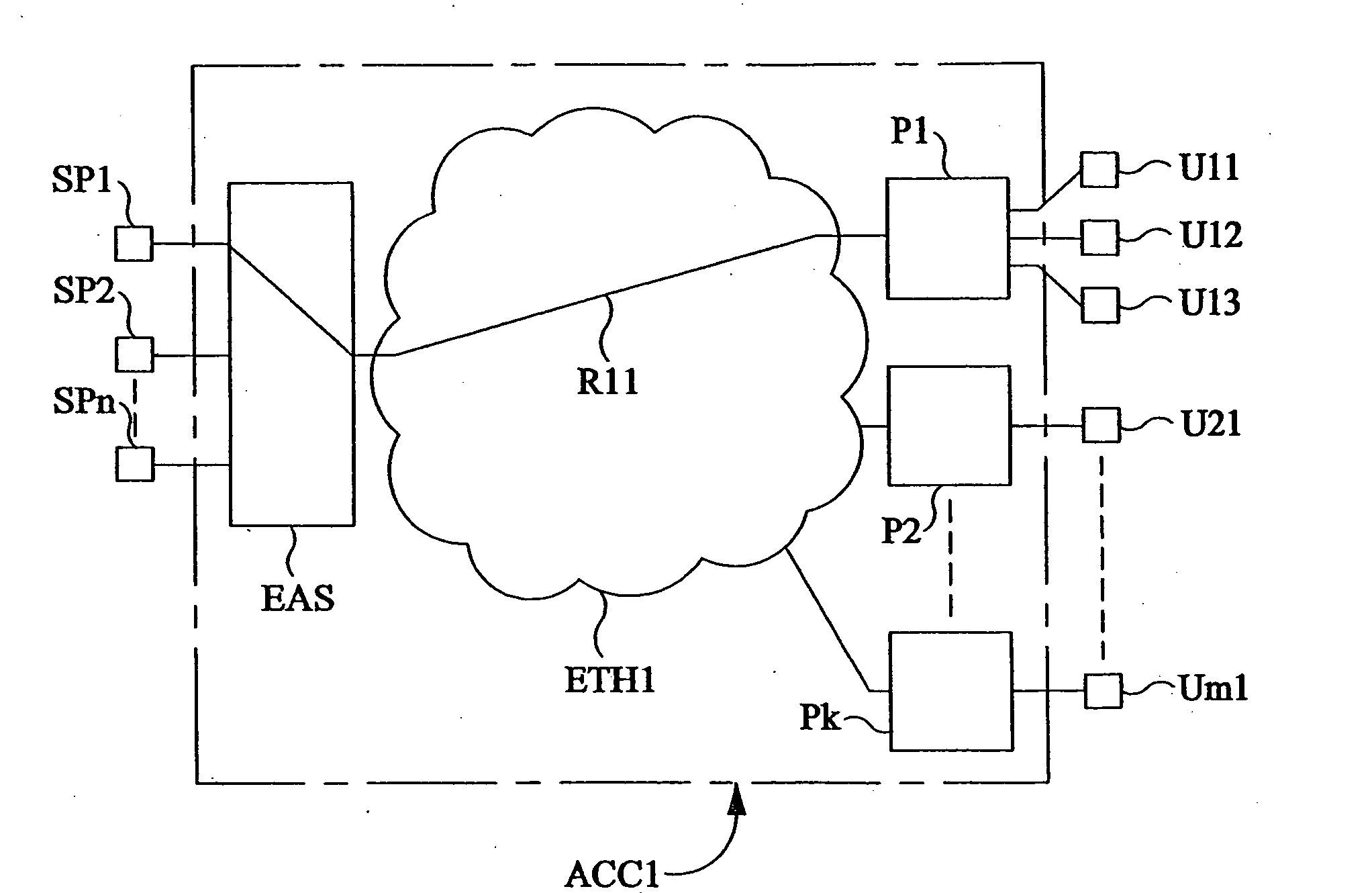
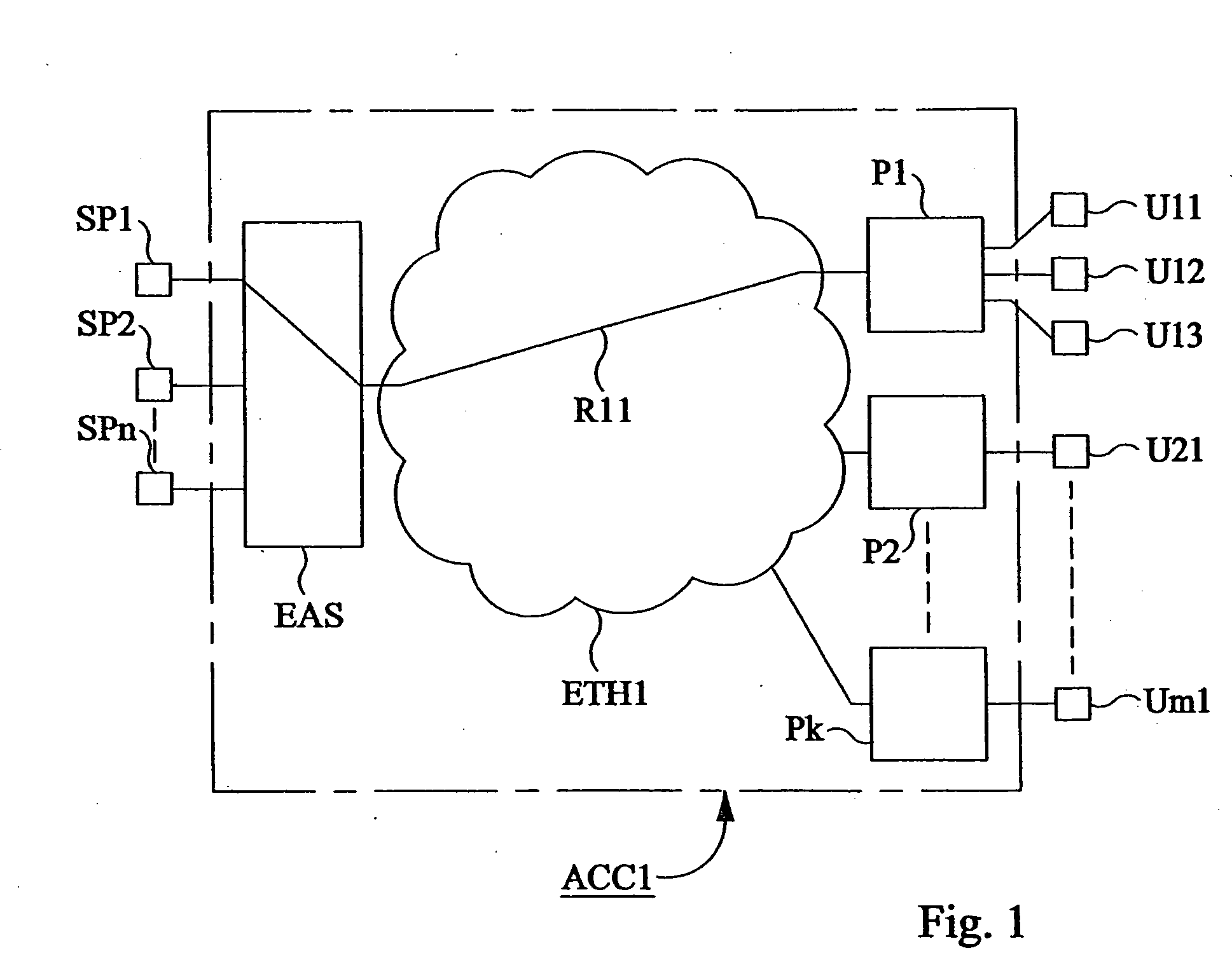
[0053]FIG. 1 shows a multiservice access system ACC1 to which users U11, U12, U13, U21, . . . , Um1 and service providers SP1, SP2, . . . , SPn are connected. An objective is to build the system such that the number of the users U11 . . . Um1 can be very great, e.g. in the range of several hundred thousands users. Another objective is that the number of the service providers SP1 . . . SPn, that each user can utilize, also is a great number, e.g. in the range of thousands of services. The access system ACC1 includes nodes P1, P2 . . . Pk, to which the users are connected with the aid of Ethernet technology. The access system also includes a node EAS, to which the service providers are connected. The node EAS is connected to the user's nodes P1-Pk via a network, which is an Ethernet based network ETH1 according to the standard IEEE 802.1q. This network is a large network and has among others a number of VLAN capable Ethernet switches, not shown in the figure. The users and the service...


PUM


Abstract

An access system (ACC1) for relating service providers (SP1-SPn) to users (U11-Um1) includes an edge access server (EAS) connecting the service providers and penults (P1-Pk) connecting the users. User devices (UD11-UD14) are connected via VLAN:s to a user port (UP11) on the penult. The edge access server has service agents (SA1-SAn), an administrator (AD1) and a broadcast handler (BH1), which forms a handling system together with handlers (H1-Hk) in the penults. A user (U11) decision including VLAN, service (SP1) and user port (UP1) is sent to the administrator (AD1), which dynamically allocates to the relevant service agent (SA1) a MAC address, defining a relation (R11). A user device (UD1) broadcasts a DHCP request unicasted together with user port (UP11) to the broadcast handler (BH1). The user device (UD11) gets its IP address and IP address to the service sgent (SAl). The device (UD11) broadcasts an ARP request which is unicasted by the penult (P1), to get the MAC address to the service agent (SA1). The MAC address has an internal structure, describing the switching route from source to destination.

Description

TECHNICAL FIELD OF THE INVENTION [0001] The present invention relates to methods and arrangements for simplifying switching in an access network. DESCRIPTION OF RELATED ART [0002] Ethernet has been developed mainly as a LAN (Local Area Network) technology, aiming to provide an efficient infrastructure for data networks within a company. Originally it was developed for moderate speed shared media, but current technology applies mainly to point-to-point links up to 10 Gbit / s, interconnected by high capacity Ethernet switches, supporting virtual LAN, VLAN, as described in the standard IEEE 802.1q. A virtual LAN is a group of system, such as computers in a workgroup, that need to communicate with each other, and protocols that restrict the delivery of VLAN frames to members of the VLAN. [0003] A LAN can be partitioned into multiple VLAN:s, where each VLAN is assigned a number called a VLAN identifier that identifies it uniquely within the LAN. A LAN contains at least one VLAN, the defau...

Claims


Application Information

Patent Timeline
Patent Type & Authority Applications(United States)
IPC IPC(8): H04L12/18H04L12/24H04L12/28H04L12/46H04L29/12
CPCH04L12/185H04L12/2861H04L12/287H04L12/4645H04L12/467H04L61/6022H04L29/12839H04L41/046H04L61/10H04L61/2015H04L29/12018H04L2101/622H04L61/5014
Inventor RINDBORG, TOMHALEN, JOACIM
Owner TELEFON AB LM ERICSSON (PUBL)
Why Eureka
Try Eureka