Method of tagging signals used for leakage detection and measurement in cable television networks and apparatus for detection and/or measurement of leakage sources tagged with this method

a technology of tagging signals and cable television networks, which is applied in the direction of electrical equipment, two-way working systems, television systems, etc., can solve problems such as signal leakage, equipment malfunction, and catv operators, and achieve the effect of simplifying the absolute magnitude measurement, minimizing the bandwidth occupied by the signal, and minimizing the level of the side bands

Inactive Publication Date: 2014-10-07
KABELKOM Z O O
View PDF5 Cites 12 Cited by
  • Summary
  • Abstract
  • Description
  • Claims
  • Application Information

AI Technical Summary

Benefits of technology

[0018]The present invention lies without limitation in the placement of a tagging signal within the bandwidth formally occupied by a digital or analog signal used for the transmission of services in a CATV network (in-use channels). At both ends of the bandwidth occupied by the signal in a particular CATV channel, there is always a guard band. There is no useful energy (coming from the modulation process) transmitted in this band. The main purpose of the guard band is the protection of adjacent channels from interference caused by that particular channel and the simplification of receiver filtering circuits. However, if a narrowband tagging signal (or signals) are placed in the guard band, the signal in that particular channel and in the adjacent channels will be unaffected. Digital data / television channels and analog television channels occupy quite a wide frequency band (6-8 MHz) and are not very susceptible to interference caused by narrowband signals. The quality of signals in the adjacent channels will not suffer from the tagging signal due to its being suppressed in the receiver filters.
[0019]According to the present invention, any narrowband signal with any type of analog or digital modulation can be used as a tagging signal. For example, a tagging signal can be a sinusoidal wave which is modulated with amplitude. The modulation frequency is low, in the range from 1 to 50 Hz, in order to minimize the bandwidth occupied by the signal. The modulation depth should not exceed 30% in order to minimize the level of the side bands. The usage of a sinusoidal wave simplifies the measurement of the absolute magnitude of the leakage by a leakage meter or detector. The narrowband tagging signal (not only sinusoidal) in the guard band can be extracted in the leakage meter or detector by means of the fast Fourier transform (FFT), the discrete cosine transform (DCT), or a very narrow bandpass filter, which attenuates the spectrum of the particular channel, the adjacent channels, and interfering signals not lying in the tagging signal band. The narrowband tagging signal substantially improves the accuracy of leakage magnitude measurements. Moreover, there is a simple relationship between the sinusoidal wave power level and the power level of a digitally modulated signal with a uniform distribution of the power spectrum density (typical power distribution for digital modulations used in CATV networks). This relationship may be used in leakage meters or detectors to find the leakage level of digital signals which is equivalent to the leakage level of a sinusoidal wave. Leakage standards (e.g., EN 50083-8 in Europe) define leakage limits for a sinusoidal wave only. The above described sinusoidal signal with amplitude modulation is one possible form of the tagging signal.
[0022]The notch filter can reduce the amplitude of the tagging signal which is assigned to the particular part of a network (a subnetwork). A leakage detector or meter can detect a leakage source localized in this subnetwork. The amplitudes of all tagging signals except the one suppressed in the notch filter will be relatively high and will create a kind of a signature typical for all leaks from this subnetwork. The signal processing circuit of the meter or detector will recognize the signature of the leak and the subnetwork.
[0023]CATV subnetworks may require only a part of the whole spectrum created in the CATV network headend or hub and transmitted in the main (trunk) network. This solution is quite common in practice. The shape of the spectrum is formed in the points connecting the subnetworks with the trunk network. Lowpass filters, bandpass filters, highpass filters, or other devices (e.g. amplifiers) suppress the unwanted parts of the spectrum. If the tagging signals are passed with the wanted spectrum part or suppressed with the unwanted spectrum part, the leakage meter or detector will be able to recognize the specific leak signature constituted of the tagging signals and determine the subnetwork with the detected leak source. The narrowband tagging signal can be extracted in the leakage meter or detector by means of a very narrow bandpass filter, which suppresses all signals not lying in the tagging signal band. It will help to minimize the likelihood of interference by signals falling within the bandwidth of the tagging signal.
[0024]The method of tagging the signals used for leakage detection and / or measurement in cable television networks, described herein, can be used in CATV networks, in which all channels are digitally modulated or which include both analog and digital channels. The method does not require an unused channel for leakage tagging, especially in CATV networks, where all transmissions are digital. Furthermore, the method allows for accurate and simple measurement of the leakage magnitude, is sensitive enough to detect an RF leak from the coaxial cable network under test and to ignore leaks or RF interferences from other sources. The method does not modify any signals transmitted in the network and allows to determine the part of the network where a leak source lies.

Problems solved by technology

One problem facing CATV operators is signal leakage.
The signals escaping from CATV networks can undesirably interfere with terrestrial radio communication systems, causing possible equipment malfunction (e.g., in civil aviation, emergency services) or problems with signal reception (e.g., interfered terrestrial TV channels).
Ingress deteriorates the quality of signals propagating in the CATV network, especially from subscribers to the headend (return path services).
However, a failure in the digital transmission is catastrophic—a subscriber may enjoy the program without any sign of a problem and suddenly experience a complete loss of the service.
A drawback of the described leakage detection method lies in its inability to distinguish CATV signals radiated by the system under test from other signals in the same frequency band.
The requirement of the unused channel frequency undesirably consumes valuable CATV network bandwidth and is unacceptable to CATV network operators today.
The method can sometimes cause undesirable signal distortion for analog TV signals.
However, the power measurement of digitally modulated signal, required for establishing the absolute magnitude of the leakage, is more complicated than the power measurement of a sinusoidal wave.
The measurement of the leak magnitude in such a broad bandwidth can give very inaccurate results.
The major drawback of all four methods is the fact that they can be used for tagging of analog television channels only.
Recently, a new problem has appeared.
The precise localization must be found by a technician and requires time and human resources.
The standard tagging methods, like these described in the U.S. Pat. Nos. 4,072,899, 4,237,486, 5,608,428, 6,118,975, 6,307,593, 6,600,515 and 6,804,826, do not allow the spatial distinguishing of the CATV network part responsible for a particular detected leak source.
They can recognize whether the leak source comes from the network under test, but cannot specify a particular network part where the leak source is localized.

Method used


Image

  • Method of tagging signals used for leakage detection and measurement in cable television networks and apparatus for detection and/or measurement of leakage sources tagged with this method
  • Method of tagging signals used for leakage detection and measurement in cable television networks and apparatus for detection and/or measurement of leakage sources tagged with this method
  • Method of tagging signals used for leakage detection and measurement in cable television networks and apparatus for detection and/or measurement of leakage sources tagged with this method

Examples


Embodiment Construction

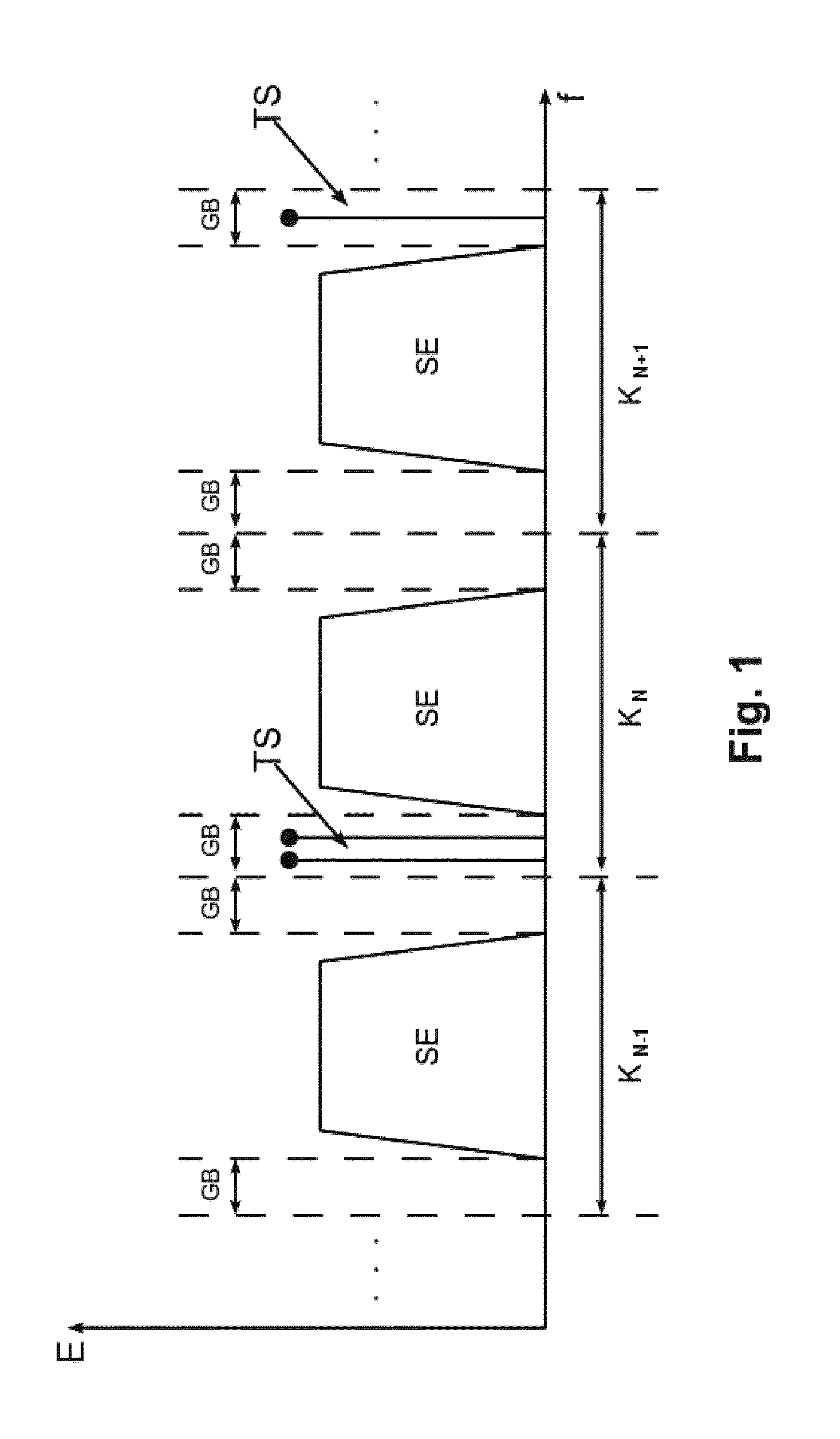
[0032]The energy E distribution in terms of frequency f, typical for digital modulations used in CATV networks, is shown in FIG. 1. The useful signal energy SE is equally distributed almost over the entire CATV channel bandwidth (FIG. 1 shows three consecutive channels KN−1, KN, KN+1. The guard band GB does not contain energy useful for service transmission. The tagging signal TS is introduced into this part of the spectrum by combining it with all signals in the headend.

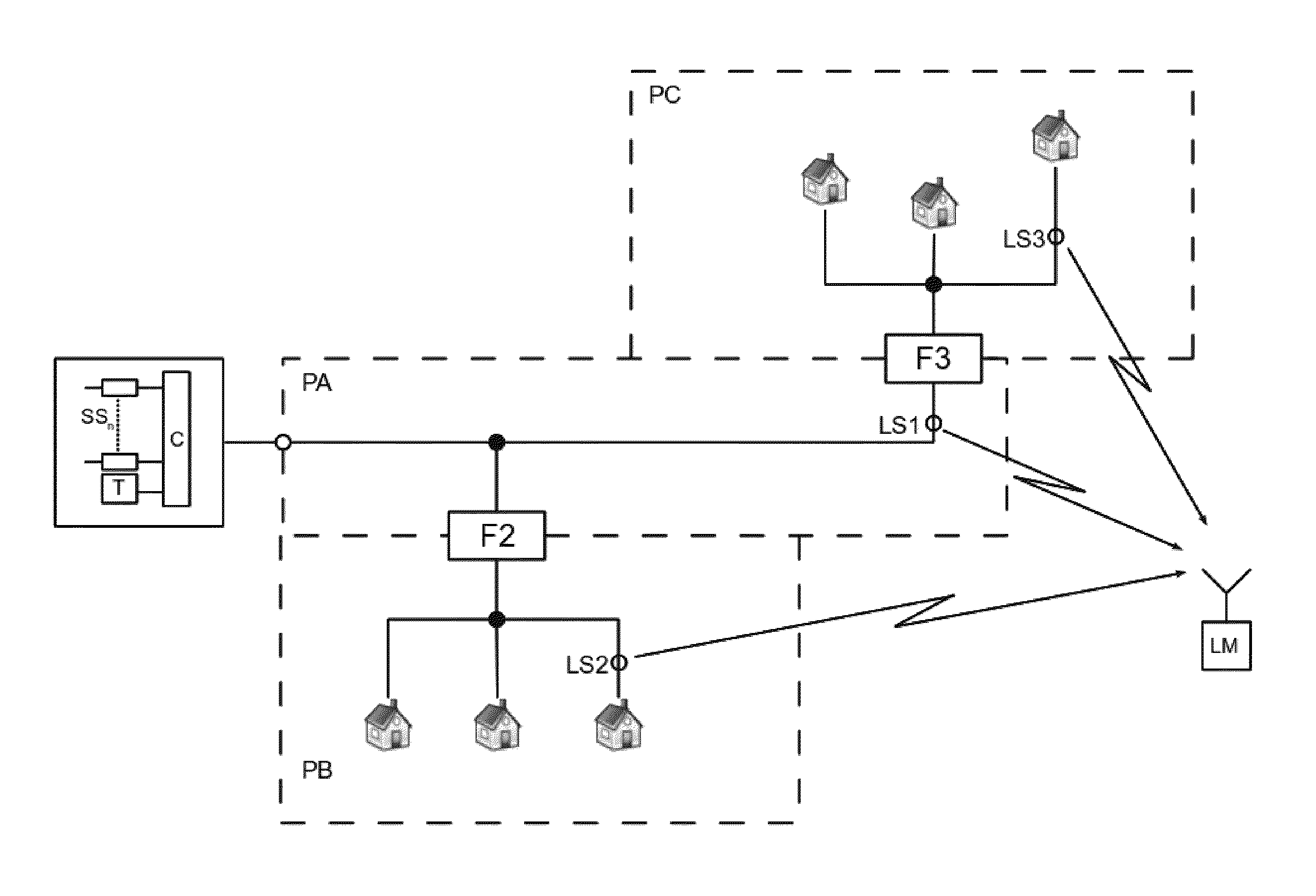
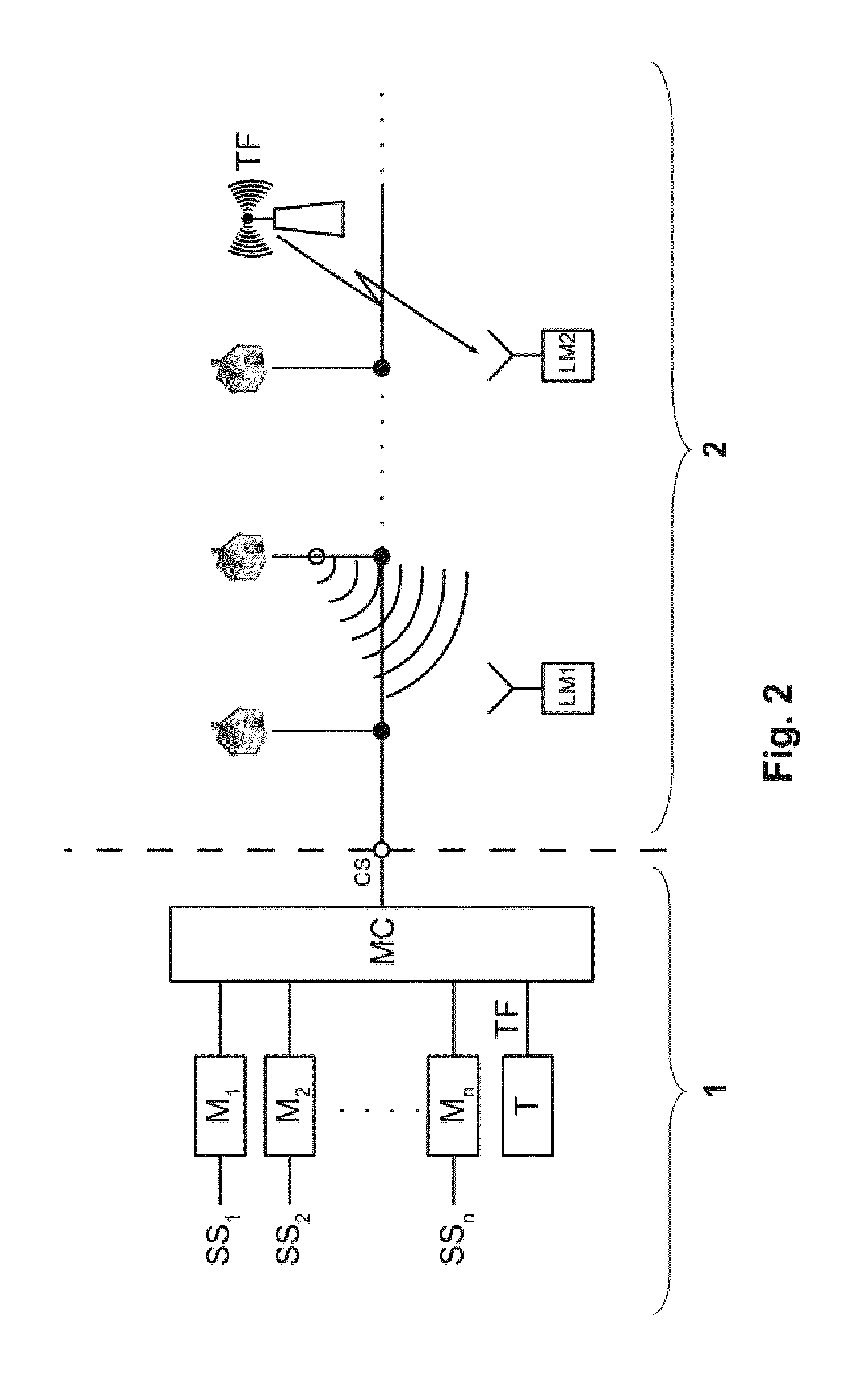
[0033]A typical CATV system shown in FIG. 2 consists of two parts. A complex CATV signal is prepared in the headend 1 for transmission to subscribers in the distribution network 2. The service sources SS1-SSn (TV, radio, video, data, etc.) are coupled to the input ports of the respective channel modulators (M1-Mn), which include carrier frequency generators. The modulators M modulate the service signals into channels for placement in the CATV network. The outputs of the channel modulators M are then coupled to the m...


PUM


Abstract

A method of tagging signals for leakage detection and measurement in cable television networks which uses additional signals carrying the tagging information and transmitted in these networks. A narrowband tagging signal or signals are placed in the unused frequency spectrum parts of any used cable television channel, in particular in the guard bands (GB) of analog or digital channels, carrying, for example, television, radio or data services.

Description

CROSS-REFERENCE TO RELATED APPLICATIONS[0001]Pursuant to 35 U.S.C §119 and the Paris Convention Treaty, this application claims the benefit of Polish Patent Application No. P.391095 filed Apr. 29, 2010, the contents of which are incorporated herein by reference.BACKGROUND OF THE INVENTION[0002]1. Field of the Invention[0003]The present invention relates to a method of tagging signals used for leakage detection and measurement in cable television networks as well as apparatus for the detection and / or measurement of leakage sources tagged with this method.[0004]2. Description of the Related Art[0005]Cable television (CATV) systems are commonly used for the transmission and distribution of television and data signals from a headend (a place where the signals are prepared for transmission out onto the cable plant) to end users (subscribers) and for the transmission of data signals (e.g. Internet or telephony) from subscribers to the headend. Coaxial cable distribution systems typically ...

Claims


Application Information

Patent Timeline
Patent Type & Authority Patents(United States)
IPC IPC(8): H04N7/173H04N17/00
CPCH04N17/00
Inventor SALA, WOJCIECHSZOSTKA, JAROSLAW
Owner KABELKOM Z O O
Why Eureka
Try Eureka