
Apparatus and method for determining timing for transmissions

a technology of transmission timing and apparatus, applied in the field of multicast transmission, can solve the problems of node b b>120/b> not being able to contribute to the soft combining of received data at the ue, incurred additional latency, and not being able to scale well to large number of node bs b>120, etc., to achieve alleviation or eliminate one

Active Publication Date: 2010-12-28
NVIDIA CORP
View PDF3 Cites 12 Cited by
  • Summary
  • Abstract
  • Description
  • Claims
  • Application Information

AI Technical Summary

Benefits of technology

This approach enables accurate timing adjustments for multicast transmissions, reducing latency and buffer requirements, and supports efficient communication in MBMS systems, even in scenarios with asymmetric links, by utilizing existing synchronization procedures and minimizing bandwidth on downstream backhaul.

Problems solved by technology

Furthermore, the ability of the Node B 120 to contribute to the soft combining for the received data at the UE is also lost.
A minor disadvantage of option (ii), when compared to option (i), is the requirement to include memory at the Node B 120 to buffer frames.
However, the disadvantage of this approach is the additional latency incurred.
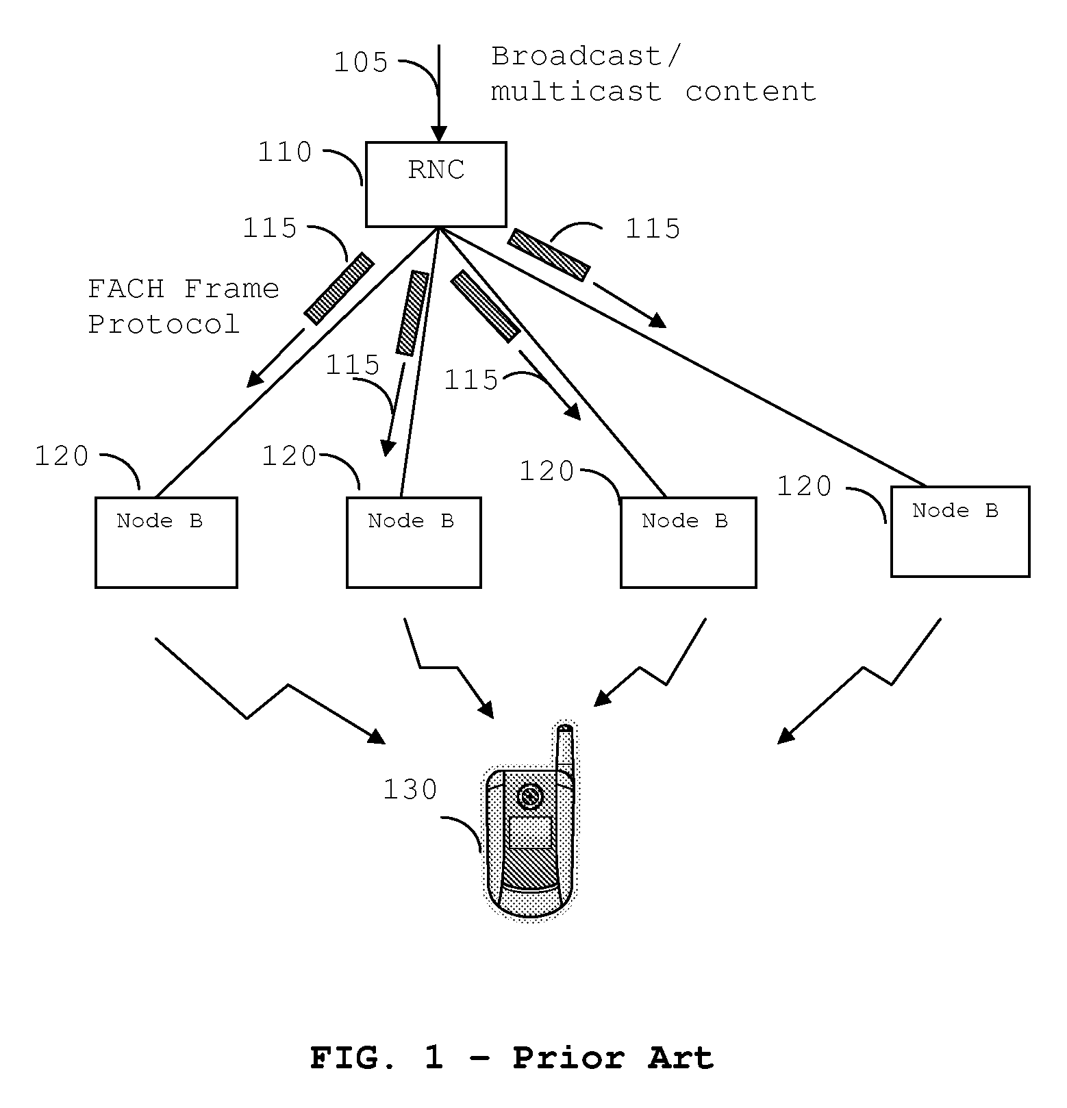
However, the architecture does not scale well to large numbers of Node Bs 120, which may be required for the broadcasting of mobile television.
One problem is that the RNC 110 needs to operate a FACH Frame Protocol user plane to each Node B 120 individually.
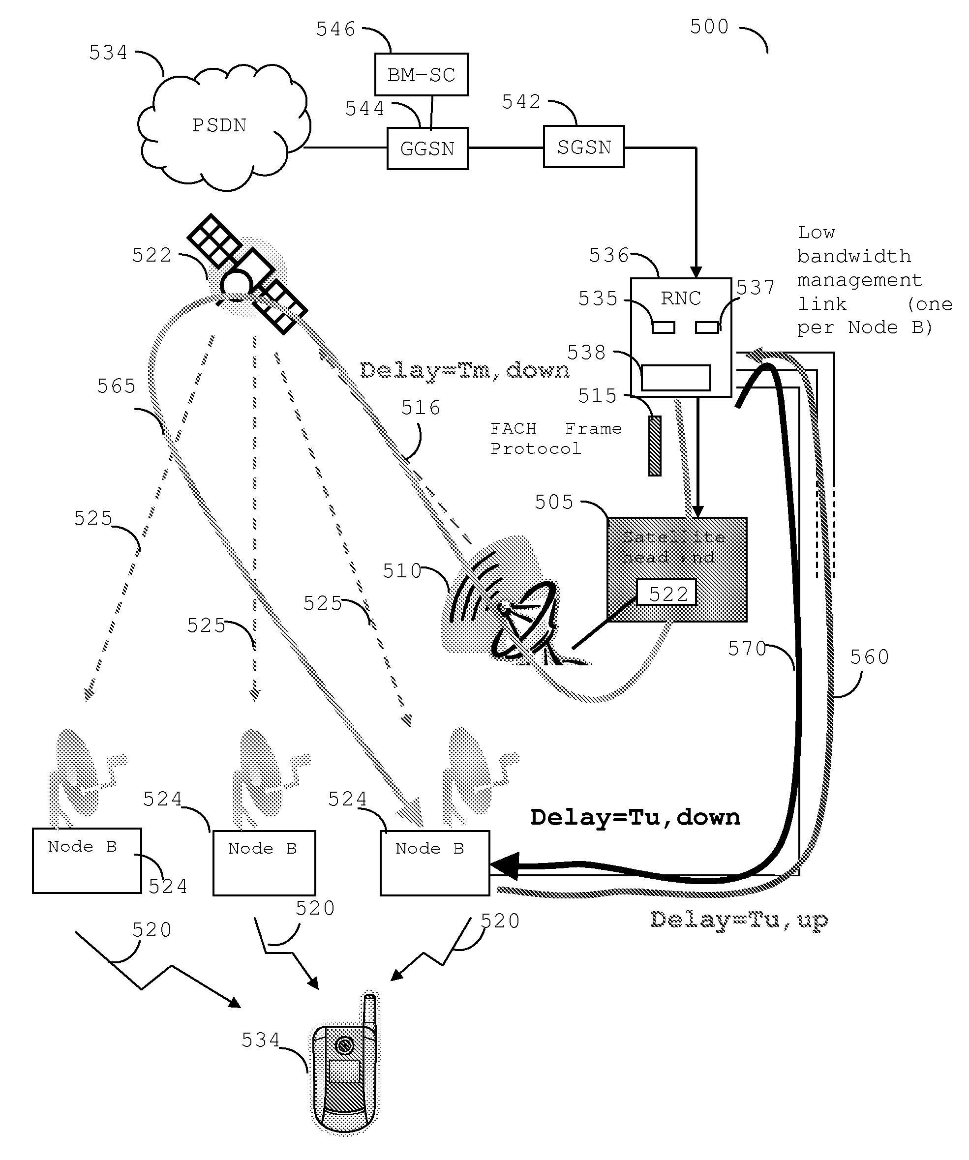
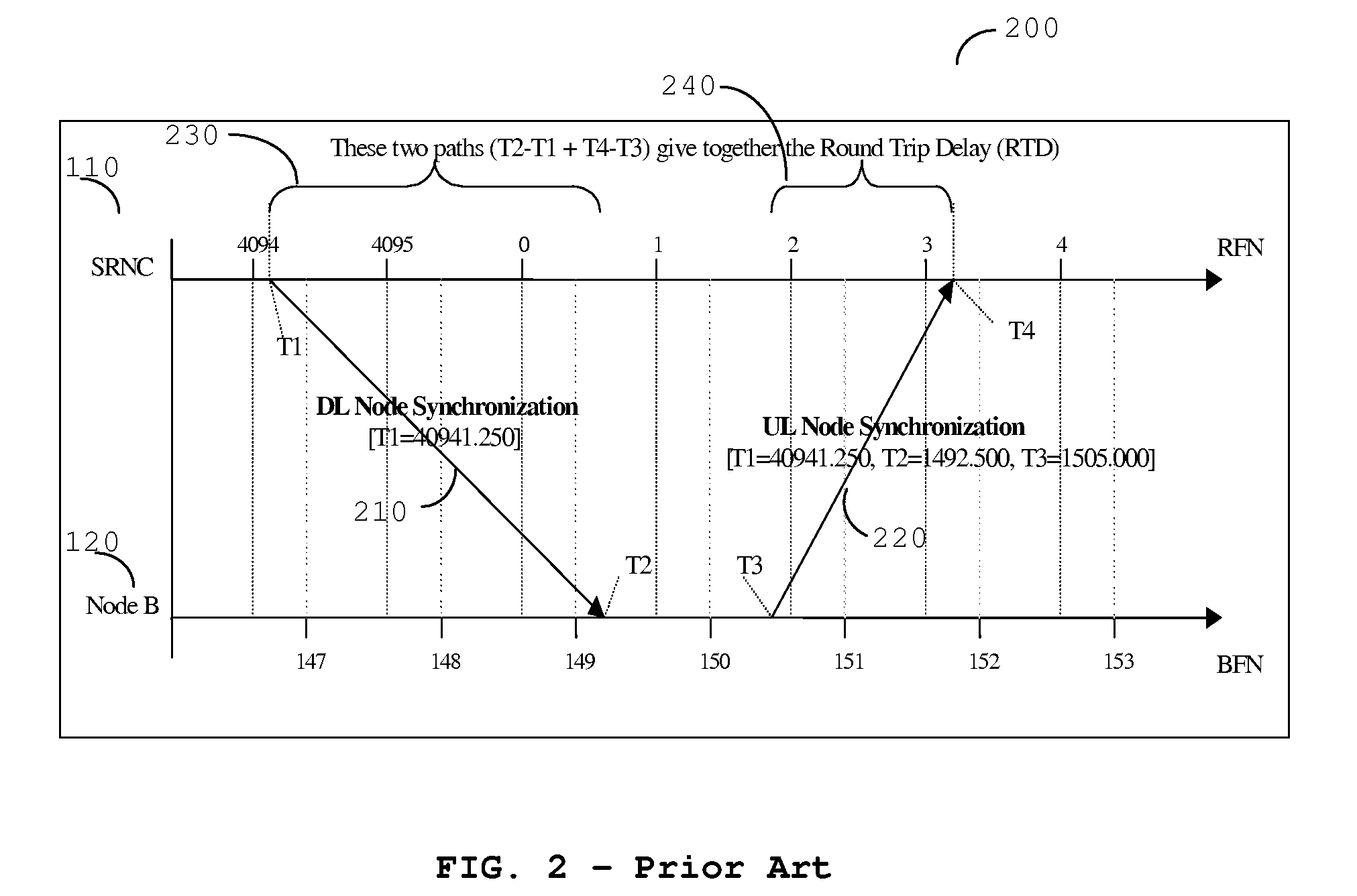
However, the round trip delay (RTD) is no longer balanced equally between downlink and uplink and the required metric cannot simply be obtained by halving the RTD.

Method used


Image

  • Apparatus and method for determining timing for transmissions
  • Apparatus and method for determining timing for transmissions
  • Apparatus and method for determining timing for transmissions

Examples


Embodiment Construction

[0053]The following description focuses on embodiments of the invention applicable to a UMTS (Universal Mobile Telecommunication System) cellular communication system, and in particular to a UMTS Terrestrial Radio Access Network (UTRAN) operating within a 3rd generation partnership project (3GPP) system. The inventive concept is concerned with the delivery of user plane content from the RNC to the Node B in a 3rd Generation Partnership Project (3GPP) Multimedia Broadcast Multicast Service (MBMS) system, as defined by 3GPP in “TS25.346—Introduction of the MBMS in the Radio Access Network”. This document provides a mechanism to deliver broadcast or multicast content to a number of subscriber devices over the 3GPP air-interfaces, time division CDMA (TDCDMA) and wideband CDMA (WCDMA).

[0054]However, it will be appreciated that the invention is not limited to the described communication system, but may be applied to other communication systems, for example to MBSFN (MBMS over a Single Fre...


PUM


Abstract

A communication network element (536) comprises a transmitter (535) for transmitting at least one timing data packet to at least one further network element (524) over both a first communication link and a second communication link and a receiver (537) for receiving two timing data packets from the at least one further network element (524) over the second communication link. The communication network element (536) further comprises signal processing logic (538) operably coupled to the transmitter and receiver and arranged to calculate a transit delay of the at least one timing data packet over the first communication link based on the received two timing data packets from the at least one further network element (524) over the second communication link, wherein the signal processing logic (538) is capable of scheduling at least one transmission across the first communication link to the at least one further network element (524) in response thereto.

Description

FIELD OF THE INVENTION[0001]The field of the invention relates to multicast transmissions in communication systems and in particular, but not exclusively, to timing of multicast transmissions for Multimedia Broadcast Multicast Service (MBMS) in a 3rd Generation Partnership Project (3GPP) communication system.BACKGROUND OF THE INVENTION[0002]Currently, 3rd generation cellular communication systems are being rolled out to further enhance the communication services provided to mobile phone users. The most widely adopted 3rd generation communication systems are based on Code Division Multiple Access (CDMA) and Frequency Division Duplex (FDD) or Time Division Duplex (TDD) technology. Further description of CDMA, and specifically of the Wideband CDMA (WCDMA) mode of UMTS, can be found in ‘WCDMA for UMTS’, Harri Holma (editor), Antti Toskala (Editor), Wiley & Sons, 2001, ISBN 0471486876.[0003]One enhanced feature being developed in the 3rd generation partnership project (3GPP) standard is ...

Claims


Application Information

Patent Timeline
Patent Type & Authority Patents(United States)
IPC IPC(8): H04L12/28
CPCH04L47/10H04L47/14H04L47/283H04L49/90H04W28/00H04W4/06H04W28/02H04W8/04
Inventor LEGG, PETER J.
Owner NVIDIA CORP
Learn More