Polarization control device, integrated circuit and method for compensating phase mismatch

a control device and integrated circuit technology, applied in the direction of polarization/directional diversity, transmission, antennas, etc., can solve the problems of insufficient space for extra antennas, many sites are crowded, so as to reduce the number of sites, alleviate the effect of one or eliminate the

Inactive Publication Date: 2013-06-20
SOCOWAVE TECH
View PDF3 Cites 33 Cited by
  • Summary
  • Abstract
  • Description
  • Claims
  • Application Information

AI Technical Summary

Benefits of technology

[0020]Accordingly, the invention seeks to mitigate, alleviate or eliminat...

Problems solved by technology

Recent trials in HSPA+ networks have uncovered a problem with capacity and coverage issues with single antenna UE (User Equipment) devices.
Furthermore, many sites are crowded and room for extra antennae is not available.
Many current UEs, will not support new upgrades to the 3G standard and are therefore unable to utilize HSPA+.
In particular, recent trials of HSPA+ networks have uncovered a problem due to a use of linear polarization (LP) transmission diversity and its effects on 3G UE devices that do not have the capability of diversity reception.
A UE device supporting only older versions of the standard may only have one receive antenna and, thus, will not be able to exploit the transmission diversity of the upgraded network.
A problem arises as the UE device is rotated or moved to a location where the second orthogonal transmission from the MIMO enabled Node B becomes much stronger than the desired first orthogonal transmission.
Furthermore, the second orthogonal transmission signal remains as an uncorrelated interferer as such a UE device is not able to process both MIMO transmissions at the same time.
The received carrier to interference plus noise ratio (CINR) may degrade the receiver performance by 10's of dBs, thereby causing communication links to be dropped and consequently reducing cell coverage area.
However, in practical systems there will be minor deviations from this perfect angular electric field vector that describes a circle.
A known problem in using LP transmissions is that the polarization of the transmitted signal antenna and the receiving signal antenna (if also an LP type) needs to have the angle of polar...

Method used


Image

  • Polarization control device, integrated circuit and method for compensating phase mismatch
  • Polarization control device, integrated circuit and method for compensating phase mismatch
  • Polarization control device, integrated circuit and method for compensating phase mismatch

Examples


Embodiment Construction

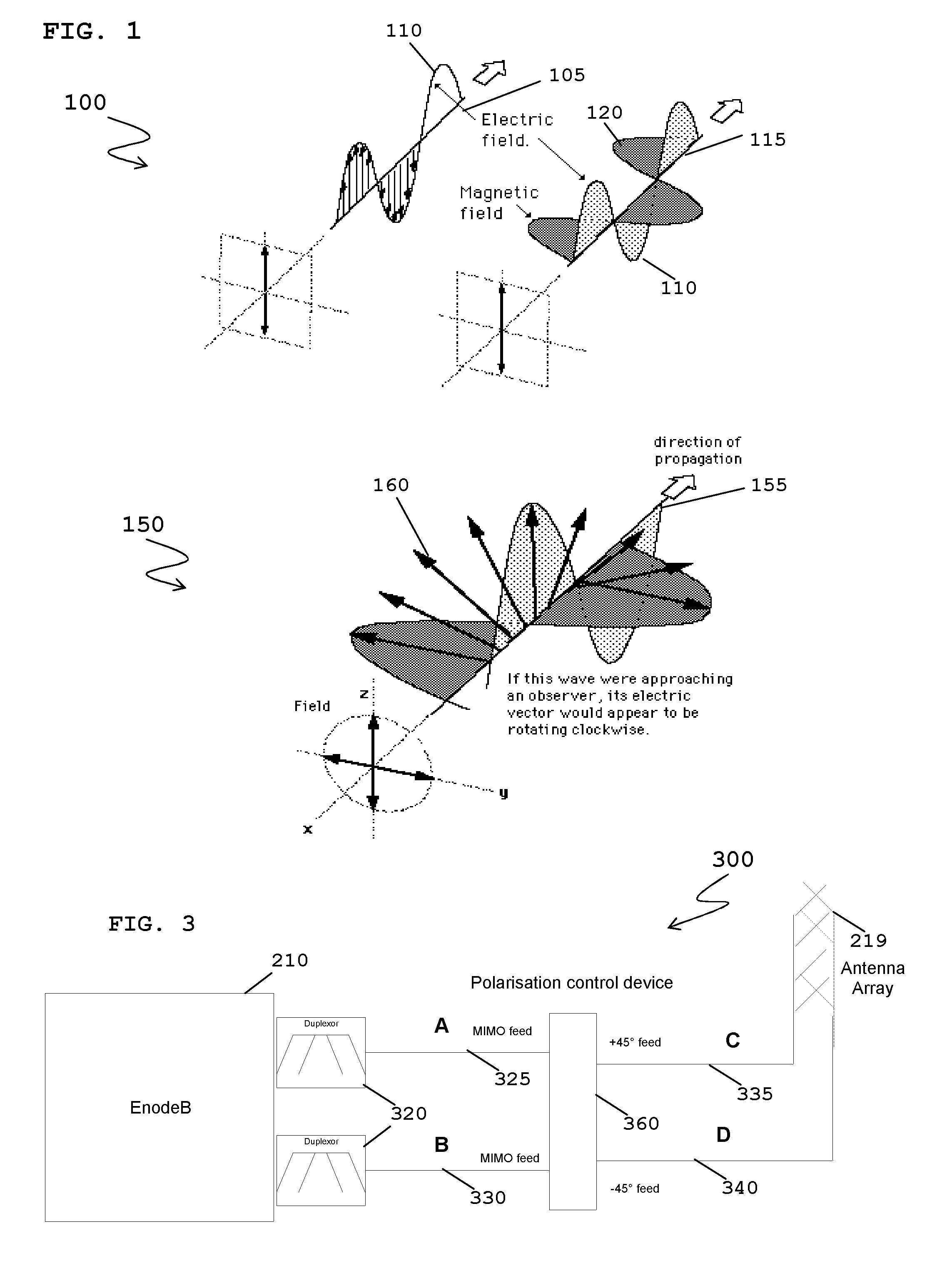
[0048]In the described examples, a reference to a native polarization of an antenna encompasses the polarization of a signal processed by one antenna element acting independently of at least one other antenna element. In the XPOL (cross polarization) example cited heretofore the native polarization would be LP (linear Polarized)+45° and LP −45°. Independent signals processed by these antenna elements will undergo no polarization transformation. When a modified version of the same signal is processed concurrently in antenna elements of both polarizations, and through combining forms a different polarization type, then this is referred to as non-native.

[0049]Modern air-interface protocols exploit antenna diversity to improve the air interface communication link. Thus, conventional antenna arrangements, and particularly antenna arrays contain an array of radiative antenna elements of for example +45° and −45° LP orthogonal polarization.

[0050]In network element-to-antenna array configur...


PUM


Abstract

A polarization control device (360) for compensating phase mismatch, wherein the polarization control device (360) is operably coupleable via at least two radio frequency (RF) feed paths to an antenna arrangement (219) that comprises at least two orthogonally polarized antenna elements. The polarization control device (360) comprises or is operably coupleable to at least one variable phase shifter (420) located on at least one RF feed path. The polarization control device (360) further comprises a processing module (490) configured to: receive and process at least one first RF signal; determine a relative phase mismatch between the at least two RF feed paths to the antenna arrangement (219) of the processed at least one first RF signal; and adjust a phase shift to be applied by the at least one variable phase shifter (420) for phase shifting at least one second RF signal applied to the at least one feed path.

Description

FIELD OF THE INVENTION[0001]The field of the invention relates to an apparatus and a method for calibrating and compensating for phase mismatch on feeds to an antenna arrangement and, in particular an apparatus and method for calibrating and compensating phase mismatch to generate alternate types of radiated signal polarization.BACKGROUND OF THE INVENTION[0002]Conventional antenna arrays, as used in cellular infrastructure macro cells, comprising multiple antenna elements and used with existing Node-B equipment in most third generation (3G) installations, utilize a fixed 65° beam pattern. Outside of the main lobe of the antenna beam the signals are spatially filtered and significantly attenuated. Conventional network planning and passive antenna array solutions process all incoming signals with a common fixed beam pattern. Such receive processing, based on signals received within the geographic area identified by the antenna beam main lobe, referred to as the RF footprint, tends to ...

Claims


Application Information

Patent Timeline
IPC IPC(8): H04W24/02
CPCH01Q3/267H01Q3/36H04B7/10H04B17/21H04B17/12H04B17/14H04W24/02H01Q3/30H01Q21/24
Inventor O'KEEFFEE, CONORO'BRIEN, MICHAEL
Owner SOCOWAVE TECH
Why Eureka
Try Eureka