
Communication unit, integrated circuit and method of diverse polarization

a communication unit and integrated circuit technology, applied in the field of antenna arrangement and, can solve the problems of minor deviation, single antenna ue receiver performance manifesting itself, and not experiencing the same processing gain as a coherent desired signal, etc., to achieve the effect of reducing, alleviating or eliminating one or two

Active Publication Date: 2012-11-15
SOCOWAVE TECH
View PDF4 Cites 34 Cited by
  • Summary
  • Abstract
  • Description
  • Claims
  • Application Information

AI Technical Summary

Benefits of technology

[0024]Accordingly, the invention seeks to mitigate, alleviate or eliminate one or more of the above mentioned disadvantages singly or in any combination.

Problems solved by technology

In addition, thermal noise from multiple sources also exhibits incoherent properties, and thus when added the signals from multiple sources do not experience the same processing gain as a coherent desired signal.
Thus, a disastrous impact on single antenna UE receiver performance manifests itself.
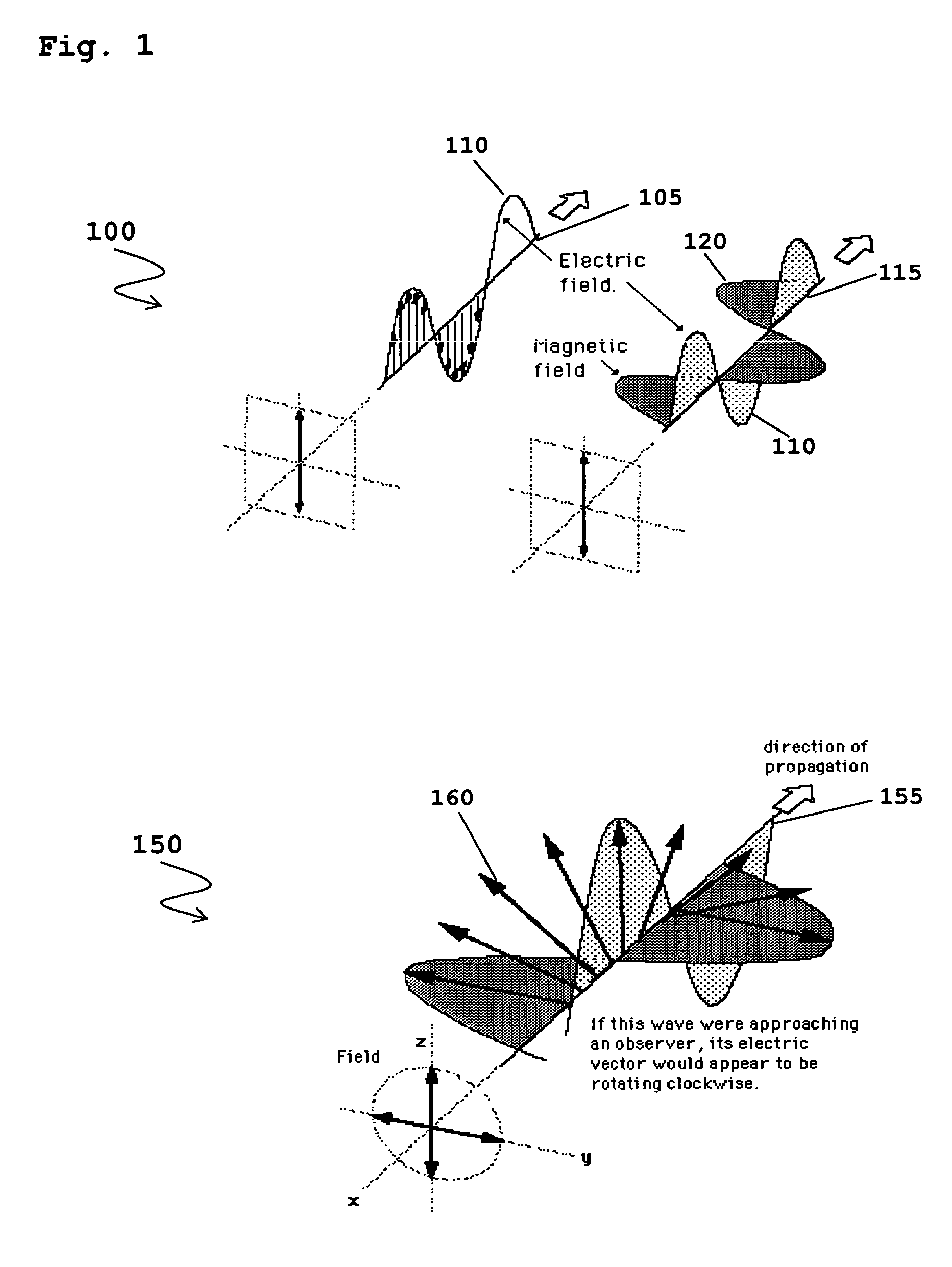
However, in practical systems there will be minor deviations from this perfect angular electric field vector that describes a circle.
A known problem in using LP transmissions is that the polarization of the transmitted signal antenna and the receiving signal antenna need to have the angle of polarization exactly the same for reception of the strongest signal.
However, an undesirable loss of around 3 dB in signal level, over the peak signal achievable with a matched LP antenna, would generally be expected of an equivalent CP antenna if receiving LP polarized wireless signals where each antenna has similar antenna gain.
Furthermore, the use of excessive processing on the signals at the antenna is undesirable, as the losses induced would be excessive and cause noise figure degradation of the receiver performance and an unacceptable loss on the PA output for transmission.
Thus, there is currently no known method of configuring an antenna polarization type using the same antenna element and supporting simultaneous reception modes of signals exhibiting different polarization types.
Furthermore, the few known techniques in configuring an antenna polarization type utilize bulky radio frequency components, which add to the complexity, size and cost.
Consequently, current techniques are suboptimal.

Method used


Image

  • Communication unit, integrated circuit and method of diverse polarization
  • Communication unit, integrated circuit and method of diverse polarization
  • Communication unit, integrated circuit and method of diverse polarization

Examples


Embodiment Construction

[0062]Embodiments of the invention are described with reference to smart (or active) antenna technology used in a wireless communication system. Since the invention can relate to any orthogonally polarized antenna arrangement, examples of the invention are equally relevant to UE or any handset receiver device. For the purpose of simplicity the following description will be explained with regard to a network element connected to an active panel antenna. Smart (or active) antenna technology is a radio technology where the antenna system comprises dedicated signal processing logic per antenna array element. Alternative embodiments may be employed in co-located antenna and signal processing units. Smart (active) antenna technologies fall into three broad families, namely: (i) multi-antenna systems (MAS); (ii) radiohead implementations with or without multiple in-multiple out (MIMO) radio ports; and (iii) active antenna arrays.

[0063]The following description focuses on embodiments of the...


PUM


Abstract

A method for processing at least one polarization type of at least one wireless signal by a communication unit operably couplable to an antenna arrangement that comprises at least two orthogonally polarized antenna elements. The method comprises processing at least one signal radiated by at least one first antenna element of the antenna arrangement; and processing the at least one signal where processing comprises at least applying at least one digital complex scaling operation on the at least one signal radiated by at least one second antenna element of orthogonal polarization to the at least one first antenna element of the antenna arrangement thereby radiating at least one wireless signal of at least one non-native polarization type.

Description

FIELD OF THE INVENTION[0001]The field of the invention relates to an antenna arrangement and method for processing polarization types of radiated signals.BACKGROUND OF THE INVENTION[0002]Wideband Code Division Multiple Access (WCDMA) communication, as used in third generation (3G) mobile cellular communications air interface technologies, is an ‘interference limited’ technology from a data throughput perspective. CDMA technology utilizes orthogonal variable spreading factor (OVSF) codes combined with pseudo noise (Pn) codes to differentiate between multiple wireless subscriber communication units (referred to as user equipment (UE) in 3G terminology) that are utilizing the same spectrum at the same time. Often, up to ninety six UEs are simultaneously supported in call mode for a specific base station (referred to as Node-B in 3G terminology). Thus, a major factor in the design of cellular communication systems, is the ability to differentiate between different communications (or com...

Claims


Application Information

Patent Timeline
IPC IPC(8): H04B7/06H04B1/38H04L27/06
CPCH01Q21/245H01Q3/2605H04B7/10
Inventor O'KEEFFE, CONORMOORE, JOE
Owner SOCOWAVE TECH
Learn More