Cyclone dust collecting device and vacuum cleaner having the same

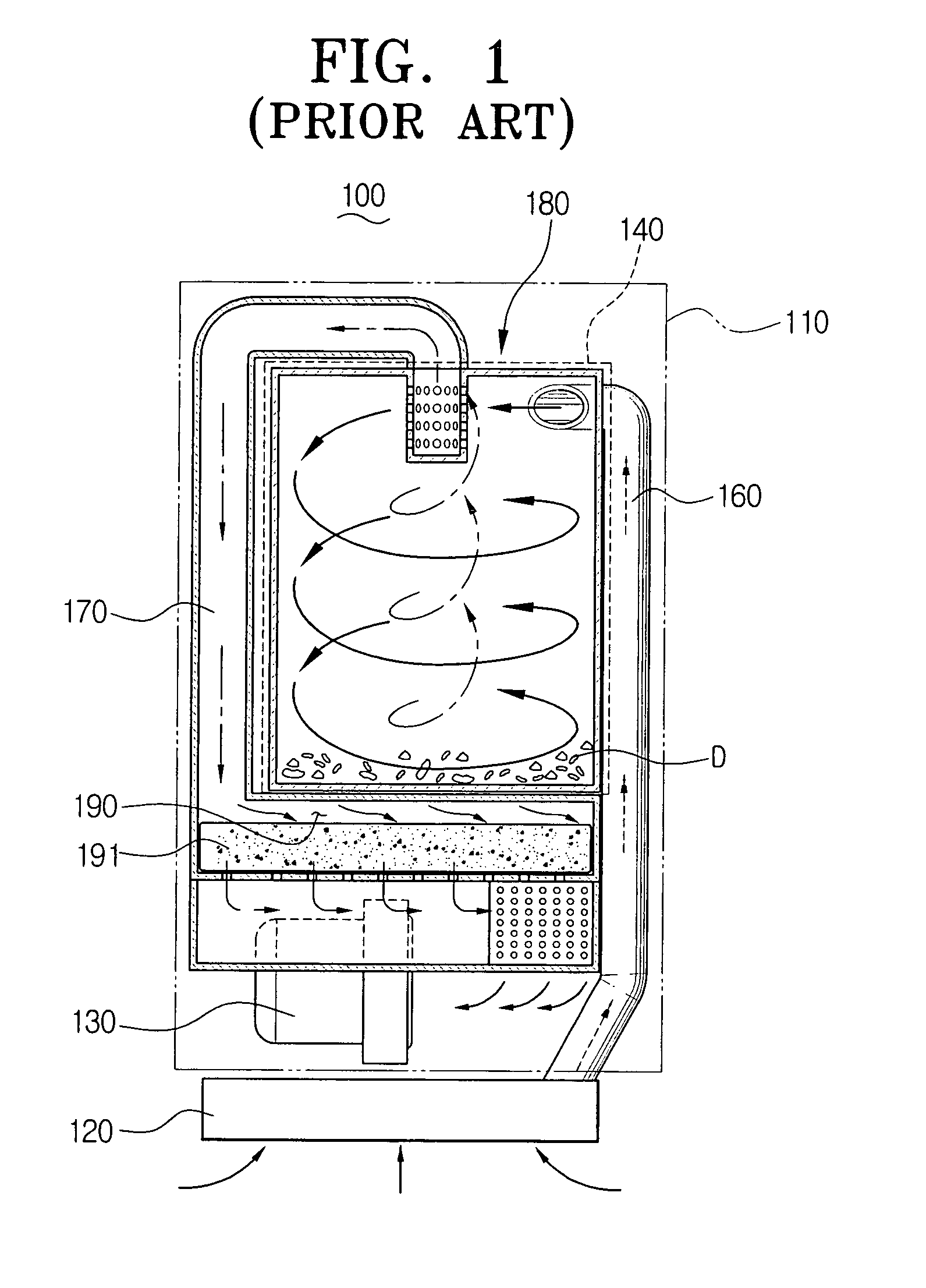
a technology of dust collecting device and vacuum cleaner, which is applied in the direction of vortex flow apparatus, cleaning filter means, separation processes, etc., can solve the problems of bulky cleaner body b>110/b>, inconvenient support of cyclone dust collecting device, and complicated manufacturing process, etc., and achieves the effect of simple structur

Inactive Publication Date: 2008-07-08
SAMSUNG GWANGJU ELECTRONICS CO LTD
View PDF23 Cites 107 Cited by
  • Summary
  • Abstract
  • Description
  • Claims
  • Application Information

AI Technical Summary

Benefits of technology

[0009]Accordingly, an object of the present invention is to provide a vacuum cleaner with cyclone dust collecting device which enables a simple-structured cleaner body.

Problems solved by technology

Hence, the cleaner body 110 is bulky and requires a complicated manufacturing process.
In addition, it is inconvenient to support the cyclone dust collecting device 180 and the filter member 191 separately.

Method used


Image

  • Cyclone dust collecting device and vacuum cleaner having the same
  • Cyclone dust collecting device and vacuum cleaner having the same
  • Cyclone dust collecting device and vacuum cleaner having the same

Examples


Embodiment Construction

[0032]Referring to the accompanying drawings, the present invention will be described according to an embodiment of the present invention.

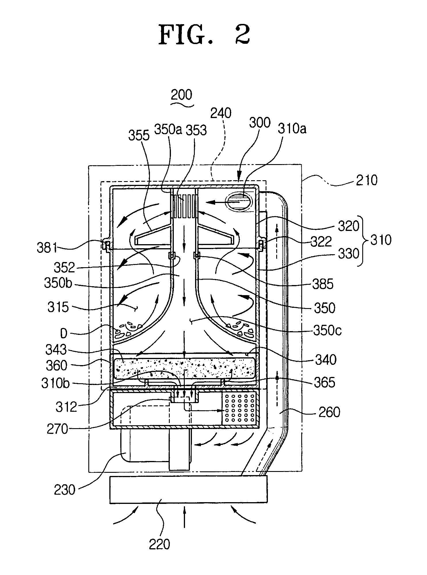
[0033]FIGS. 2 and 3 are views illustrating an upright-type vacuum cleaner, by way of example, having a cyclone dust collecting device according to an embodiment of the present invention.

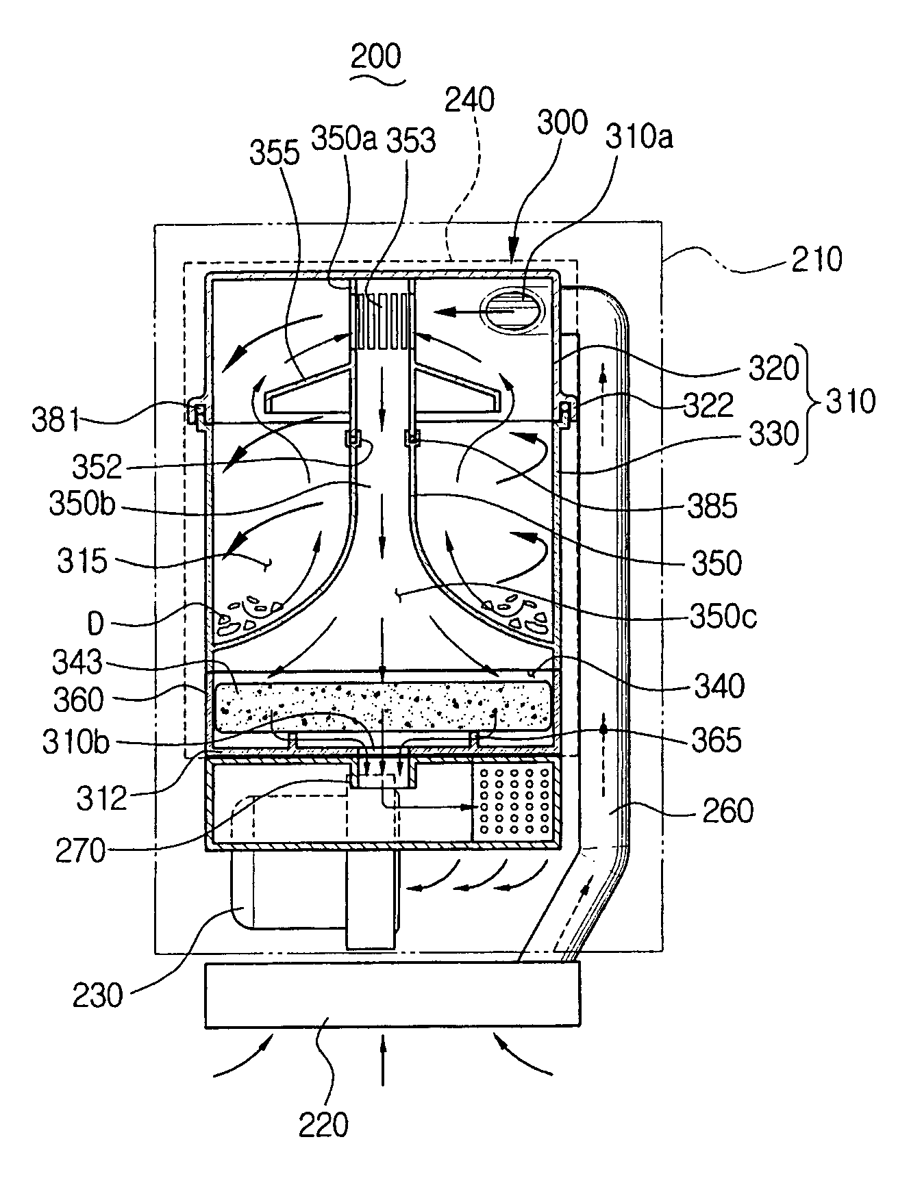
[0034]Referring to FIGS. 2 and 3, a vacuum cleaner 200 includes a cleaner body 210, a suction port assembly 220, first and second air inlet paths 260 and 270, and a cyclone dust collecting device 300.

[0035]The cleaner body 210 has a vacuum generator 230 and a dust collecting chamber 240 on which the cyclone dust collecting device 300 is detachably mounted. The dust collecting chamber 240 is interposed between the first and second air inlet paths 260 and 270. The first air inlet path 260 is connected to the suction port assembly 220. The second air inlet path 270 is connected to the vacuum generator 230. The vacuum generator 230 is disposed under a lower portion of ...


PUM

PropertyMeasurementUnit
diameteraaaaaaaaaa
conical shapeaaaaaaaaaa
adhesionaaaaaaaaaa

Abstract

The vacuum cleaner having a suction port assembly and a dust collecting chamber includes a first air inlet path to connect the suction port assembly and the dust collecting chamber, a second air inlet path to connect a lower end of the dust collecting chamber and a vacuum generator, a cyclone dust collecting device detachably mounted in the dust collecting chamber so that an upper end is connected to the first air inlet path and a lower end is connected to the second air inlet path, and a filtering chamber integrally formed with the cyclone dust collecting device and having a filter member detachably disposed. As the second air inlet path requires less space, it is feasible to easily manufacture the vacuum cleaner and maintain the filtering chamber and the cyclone dust collecting device at a time. Therefore, maintenance of the vacuum cleaner becomes more convenient.

Description

REFERENCE TO RELATED APPLICATION[0001]This application claims priority to Korean Patent Application No. 2003-32152, filed May 21, 2003 in the Korean Intellectual Property Office, which is incorporated herein by reference in its entirety.CROSS-REFERENCE TO RELATED APPLICATIONS[0002]This application is related to copending applications entitled “Filter Cleaning Device of Cyclone Vacuum Cleaner” (Korean Application No. 2003-19951, filed Sep. 9, 2003), “Cyclone-Type Dust Collecting Apparatus for Vacuum Cleaners” (Korean Application No. 2002-0077811, filed Sep. 12, 2003), and “Cyclone Type Dust Collecting Apparatus for Vacuum Cleaner” (Korean Application No. 2003-33167, filed Oct. 10, 2003) whose disclosures are commonly owned by the same assignee as the present applications and are entirely incorporated herein by reference.FIELD OF THE INVENTION[0003]The present invention generally relates to a vacuum cleaner, and more specifically, to a cyclone dust collecting device of the vacuum clea...

Claims


Application Information

Patent Timeline
Patent Type & Authority Patents(United States)
IPC IPC(8): A47L9/16B01D45/12A47L5/28A47L9/12B01D50/00B04C5/103B04C5/12B04C5/13B04C9/00
CPCA47L5/28A47L9/122A47L9/1608A47L9/1666B04C5/103B04C5/12B04C5/13B04C9/00A47L9/1683B04C2009/004A47L9/16
Inventor OH, JANG-KEUN
Owner SAMSUNG GWANGJU ELECTRONICS CO LTD
Why Eureka
Try Eureka