Hydrant box

a technology for encasing walls and hydrants, applied in water installations, thin material processing, construction, etc., can solve the problems of detracting from the aesthetic quality of the face plate, weld lines, and the face plate itself is not sufficiently extended past the edge of the box, so as to achieve uniform and aesthetic appearan

Active Publication Date: 2008-07-08
ZURN INDS
View PDF7 Cites 4 Cited by
  • Summary
  • Abstract
  • Description
  • Claims
  • Application Information

AI Technical Summary

Benefits of technology

[0011]The present invention does not require the use of welding any frame to the existing face plate of the wall hydrant box. Instead, the unitary front plate is substituted for the face plate and the frame, thereby providing a uniform and aesthetic look to the front of the wall hydrant box.

Problems solved by technology

Previous face plates did not sufficiently extend past the edge of the box to conceal any portion of a ring that was attached to the back of the box.
The welding of the additional frame 20 results in weld lines, which detract from the aesthetic quality of the face plate 18.
Additionally, the process of welding requires additional work time to be expended.

Method used


Image

  • Hydrant box
  • Hydrant box
  • Hydrant box

Examples


Embodiment Construction

[0020]For purposes of the description hereinafter, the spatial or directional terms, such as “front,”“rear,” and derivatives thereof, shall relate to the invention as it is oriented in the drawing figures. However, it is to be understood that the invention may assume various alternative variations, except where expressly specified to the contrary. It is also to be understood that the specific apparatus illustrated in the attached drawings, and described in the following specification, is simply an exemplary embodiment of the invention. Hence, specific dimensions and other physical characteristics related to the embodiment disclosed herein are not to be considered as limiting. The present invention will be described with reference to the accompanying figures, wherein like reference numbers correspond to like elements throughout.

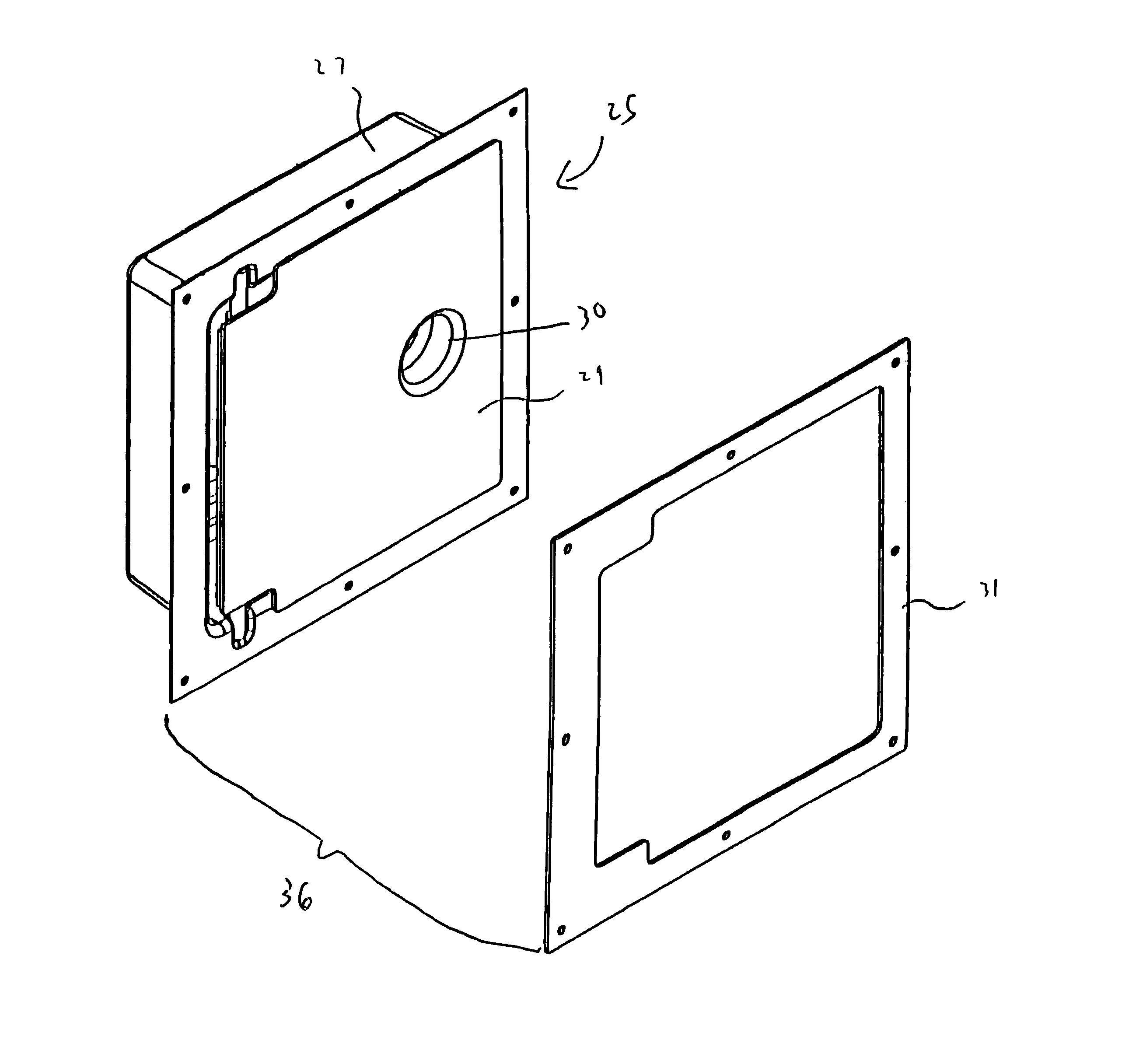
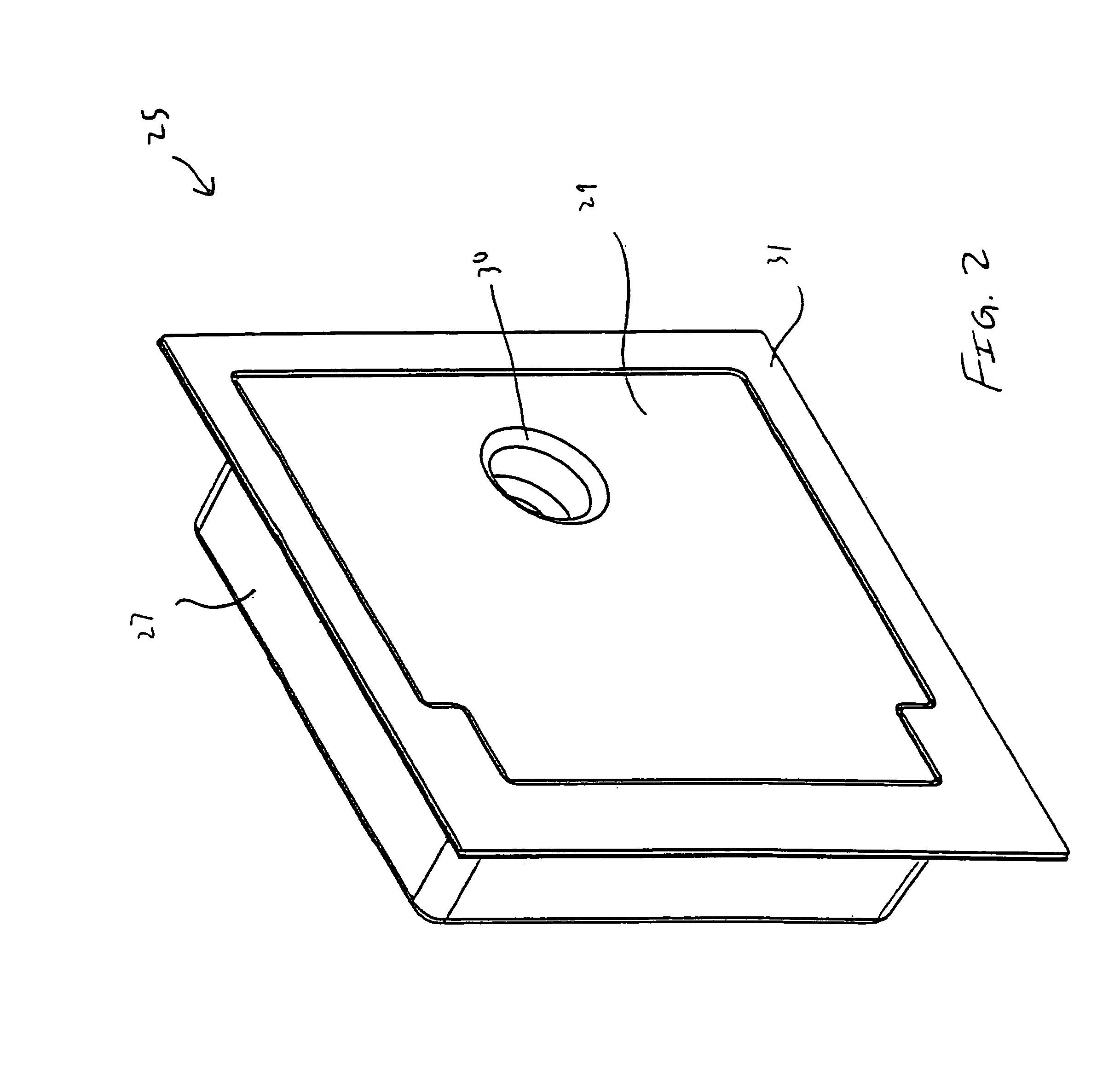
[0021]With reference to FIG. 2, a wall hydrant box 25 includes a box 27, a cover 29 and a face plate 31. Box 27 may be constructed of stainless steel and is d...


PUM


Abstract

The present invention is a wall hydrant box having a unitary front plate welded onto a front portion of the wall hydrant box. The unitary front plate is sufficiently sized to allow a ring or any other such structure to be mounted to a rear portion of the wall hydrant box, so that the structure is obscured when the wall hydrant is viewed from the front. The unitary front plate also provides a uniform and aesthetic look to the front of the wall hydrant box.

Description

CROSS REFERENCE TO RELATED APPLICATIONS[0001]This application claims the benefit of U.S. Provisional Patent Application No. 60 / 556,908, filed Mar. 26, 2004, entitled “Hydrant Box”, the disclosure of which is hereby incorporated by reference.BACKGROUND OF THE INVENTION[0002]1. Field of the Invention[0003]The present invention is directed to a wall hydrant and, more specifically, to an encased wall hydrant having a unitary front plate.[0004]2. Description of Related Art[0005]Wall hydrants are designed for commercial applications such as office buildings, institutions, hospitals, malls, retail outlets, and schools. Such wall hydrants may be encased within a box, such as a stainless steel box that is mounted within a wall. The box includes a hinged cover with an operating key lock. A face plate surrounding the cover is welded onto the box. Previous face plates did not sufficiently extend past the edge of the box to conceal any portion of a ring that was attached to the back of the box. ...

Claims


Application Information

Patent Timeline
Patent Type & Authority Patents(United States)
IPC IPC(8): F16L5/00
CPCE03C1/021Y10T137/6977Y10T137/698
Inventor LAWSON, DAVID L.DIMMER, ROBERT K.
Owner ZURN INDS
Why Eureka
Try Eureka