Filter element with vent orifice and assembly therefore

Active Publication Date: 2008-07-08
PARKER INTANGIBLES LLC
View PDF22 Cites 16 Cited by
  • Summary
  • Abstract
  • Description
  • Claims
  • Application Information

AI Technical Summary

Benefits of technology

[0013]The housing body is also sized so that it closely receives the filter element, and in particular, the first end cap of the filter element. An orientation device (rib, ridge, tab, etc.) is provided on the inside surface of the housing that engages the orientation device on the first end cap after the cover is screwed down a predetermined amount on the housing. The orientation devices on the housing and first end cap of the filter element properly rotationally orient the filter element relative to the housing such that the vent orifice is at its uppermost (top) position on the second end cap. The retaining devices on the cover and on the second end cap of the filter element are dimensioned and configured so that when the orientation devices interact to rotationally fix the filter element relative to the housing, the cover can rotate relative to the element to fully tighten the cover down onto the housing.
[0015]When a spent element is to be removed from the housing, the above procedure is reversed. That is, the cover is unscrewed and removed from the housing. When the element is pulled out from the housing such that the orientation device on the first end cap is separated from the orientation device on the housing, the element again is temporarily retained on the cover by the interaction of the retaining devices on the second end cap and cover, such that the cover and element can be removed as a subassembly. The element can then be easily removed from the cover and replaced with a fresh element.
[0016]As such, the present invention thereby provides a filter element and assembly for fluid applications which require a purging of air, and particularly for such applications where the filter element is horizontally oriented (side-loaded), where the filter element is rotationally positioned such that the vent orifice is properly located for bleeding air from the filter element as the element fills with fluid.

Problems solved by technology

The constant purging of air in the housing does not significantly effect the particulate and contaminant separating functions of the filter, but it can impact the water-removing properties of the media, as the flow is forced through a relatively small portion of the media at a high rate, rather than being spread over a wide surface area.
Any bypass of unfiltered fuel is fairly insignificant and can be caught by secondary filters downstream.
While the above solution has received some acceptance with vertically-oriented filter elements, it does not address the issue with horizontally oriented (side-loaded) filter elements.
When the filter rotates, it can be difficult to anticipate and control the final location of the vent orifice, and hence to position the vent orifice such that it allows a maximum amount of air to vent from the element.
As should be appreciated, positioning the vent orifice, for example, at the bottom or near the bottom of the element will not allow air to be purged from the element.

Method used


Image

  • Filter element with vent orifice and assembly therefore
  • Filter element with vent orifice and assembly therefore
  • Filter element with vent orifice and assembly therefore

Examples


first embodiment

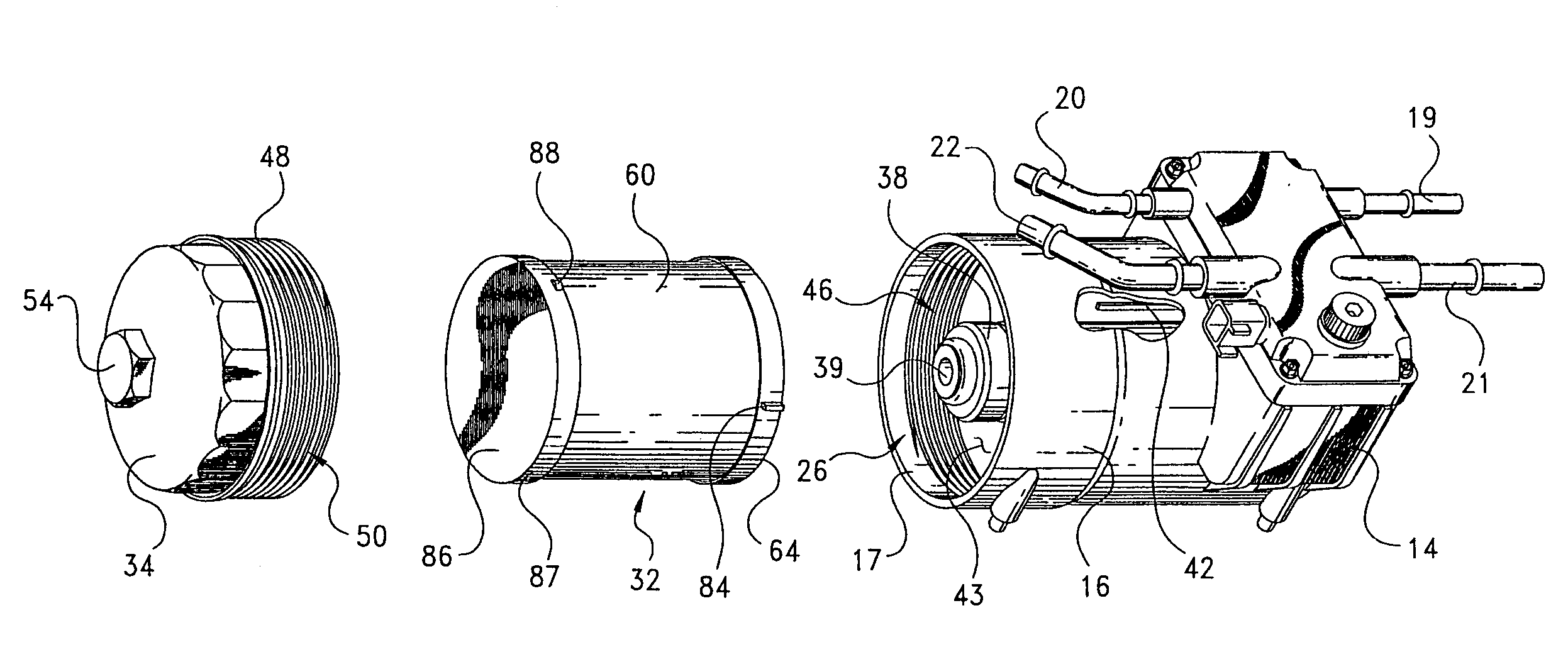
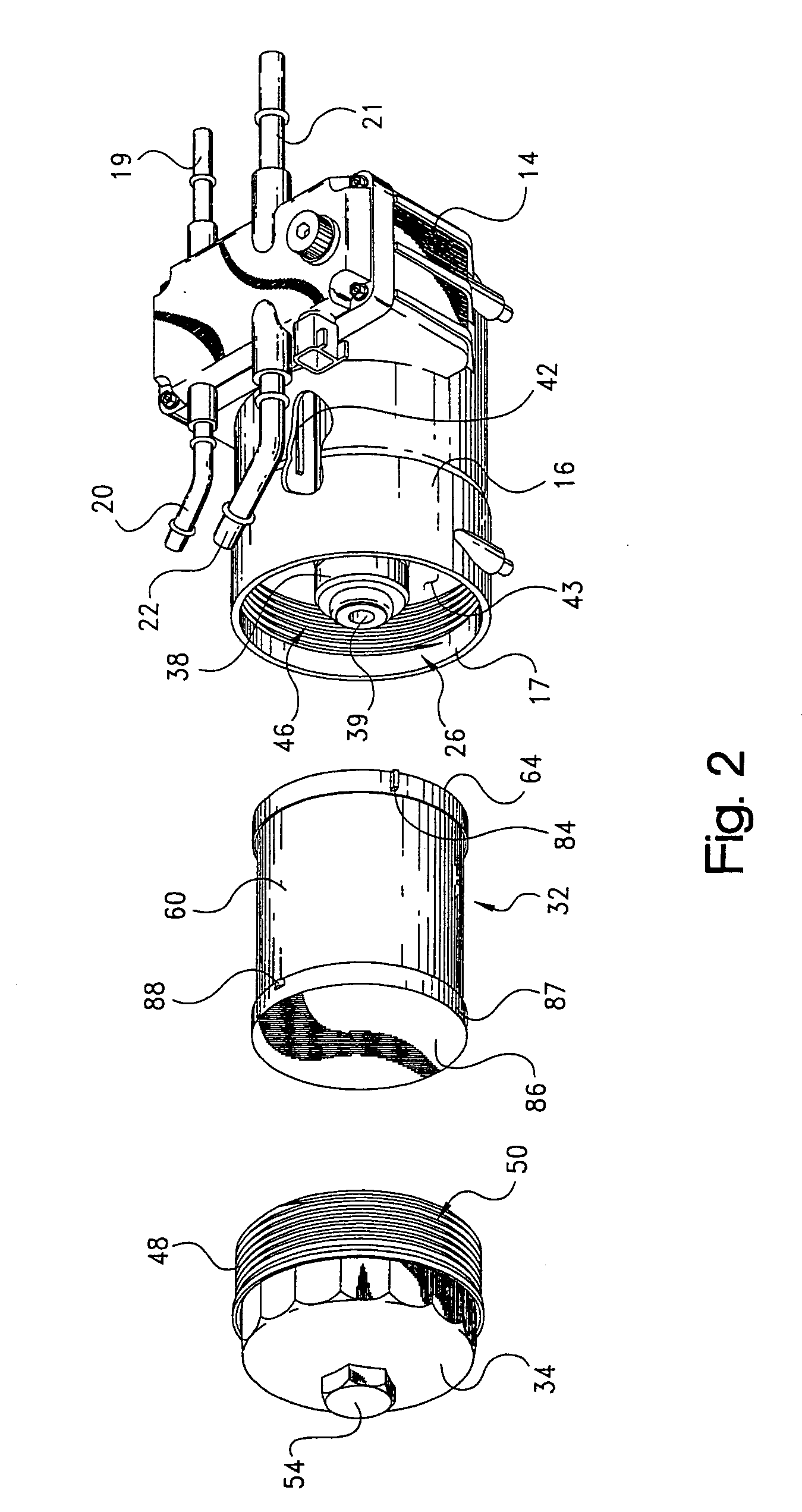
[0040]The filter element also includes a second, circular end cap 86 sealingly bonded to the second end of the media ring. A short sleeve 87 extends axially from the periphery of the end cap toward the opposite end of the element, and outwardly bounds the media 60. one, and preferably two retaining devices as at 88 are fixed to and integral with the second end cap and project radially outward therefrom, from opposite sides of the second end cap. Preferably the retaining devices on the second end cap each comprise a rib, tab, ridge or other radially outward projecting element fixed to the end cap. The retaining devices 88 are preferably formed unitary (in one piece) with the second end cap, but they could also be formed as separate pieces and then attached to the end cap in an appropriate manner. The reasons for the retaining devices 88 will also be described in more detail below.

[0041]End caps 64, 86 are formed of appropriate impervious material for the particular application, such...

second embodiment

[0047] shown in FIGS. 8 and 9, the second end cap 86 of the filter element can include a series of axially-extending flexible fingers, tabs or other elements 92 which interengage with a lip 94 on the inside of cover 34 to retain the element to the cover during initial assembly. The number, length and spacing of fingers 92 can vary depending upon the particular application, as should be appreciated. The interaction between the fingers 92 and lip 94 is such that when the cover is initially screwed onto housing 16 a pre-determined amount (preferably half-way) such that orientation devices 42, 84 interengage as described above, and the element becomes rotationally fixed relative to the housing, the cover 34 can then turn relative to the element, as the cover is fully tightened down onto the housing. As before, when the element is spent and needs to be replaced, and the cover is screwed off the housing in the same manner as described above, the element can be easily removed from the cove...


PUM

PropertyMeasurementUnit
Flexibilityaaaaaaaaaa
Distanceaaaaaaaaaa

Abstract

A filter element and assembly for fluid applications which require a purging of air, and particularly for applications where the filter element is horizontally oriented (side loaded), where the filter element is rotationally positioned relative to the housing such that a vent orifice is properly located for venting air from the filter element as the element fills with fluid. The housing includes a cylindrical body with a closed end a threaded open end, and a threaded, cup-shaped cover which is screwed down onto the housing. The filter element and housing include i) cooperating retaining devices which temporarily couple the filter element to the housing cover when the element is initially inserted into the housing and the cover is initially screwed onto the housing; and ii) cooperating orientation devices which rotationally orient the filter element in the housing as the housing cover is further and fully screwed down onto the housing.

Description

CROSS-REFERENCE TO RELATED CASES[0001]The present application claims the benefit of the filing date of U.S. Provisional Application Ser. No. 60 / 450,393, filed Feb. 26, 2003; and U.S. Provisional Application Ser. No. 60 / 479,032, filed Jun. 17, 2003, the disclosures of which are expressly incorporated herein by referenceFIELD OF THE INVENTION[0002]The present invention relates generally to fluid filters and filter assemblies, and more particularly to a fuel filter and assembly for a vehicle fuel system.BACKGROUND OF THE INVENTION[0003]In certain fuel systems, such as for vehicles, a pump is provided to move fuel through the system such as from the tank to the engine. A filter element is typically provided upstream (on the vacuum side) of the pump to protect the working components of the pump, as well to protect other downstream components. When the pump is initially primed, air in the filter housing is purged to the extent of the fuel flow through the filter element. When the element ...

Claims


Application Information

Patent Timeline
IPC IPC(8): B01D35/00B01D35/28B01D29/21B01D35/01B01D36/00
CPCB01D29/21B01D36/001B01D29/96B01D2201/295B01D2201/4046B01D2201/4076
Inventor KNIGHT, STEVEN R.
Owner PARKER INTANGIBLES LLC
Why Eureka
Try Eureka