
Wireless traffic control system

a traffic control system and wireless technology, applied in the direction of signaling systems, controlling traffic signals, instruments, etc., can solve the problems of affecting the effectiveness of providing traffic control information to drivers, elderly drivers may not see or process the information on traffic control signs, and loss of attention to the information provided on traffic control signs

Active Publication Date: 2008-07-08
ARRIVER SOFTWARE LLC (N D GES D STAATES DELAWARE)
View PDF21 Cites 41 Cited by
  • Summary
  • Abstract
  • Description
  • Claims
  • Application Information

AI Technical Summary

Benefits of technology

"The patent describes a method and system for using traffic control signs to communicate information wirelessly between them. This can include things like traffic control information and vehicle information. The system includes multiple traffic control signs that can communicate with each other. The technical effect of this is that it allows for more efficient and effective communication between traffic control signs, which can improve traffic control and safety on the road."

Problems solved by technology

However, external factors may affect the effectiveness of providing this information to drivers.
For example, elderly drivers may not see or process the information on a traffic control sign as readily as younger drivers.
Further, sleepiness and / or driver fatigue may result in a loss of attention to the information provided on traffic control signs.
In other instances, environmental factors may affect the effectiveness of providing this information.
For example, hilly terrain or outgrowth of plants and trees may obscure traffic control signs from a driver, thereby resulting in the information on the sign never being seen by a driver or seen too late.
Weather conditions also may obscure traffic control signs and, for example, limit the distance from which a driver can view the information on a sign.
Additionally, depending on the driver and vehicle, the placement or positioning of traffic control signs may not provide drivers with enough warning regarding an upcoming condition (e.g., sharp curve or lane closed ahead) to allow the driver to properly react to the information posted on the traffic control sign.
Also, the spacing between traffic control signs may not allow for proper response by a driver, for example, if the traffic control signs are too close together or too far apart.
Further, there is typically no means to provide information to a driver if the driver, for example, does not see a traffic control sign (e.g., driver fails to see a sharp curve sign) and passes the sign.
Also, there is typically no means to provide information to a driver relating to a traffic control sign based on upcoming conditions (e.g., work zone ahead posted on a traffic sign with a stopped vehicle in the work zone).
Thus, the effectiveness of traffic control signs to provide information to drivers is often reduced by factors or circumstances such as the placement or positioning of the signs, driver incompetence, driver age, indifference or inattention, roadway limitations or impairments and / or weather conditions.
Reduction or limitation of the ability to view these signs, as well as improper positioning of these signs, decreases the effectiveness of the signs and may increase the likelihood of accidents or other undesirable or unintended consequences.
Further, many signs do not provide adequate notice regarding upcoming conditions because of the permanent nature of the signs.

Method used


Image

  • Wireless traffic control system
  • Wireless traffic control system
  • Wireless traffic control system

Examples


Embodiment Construction

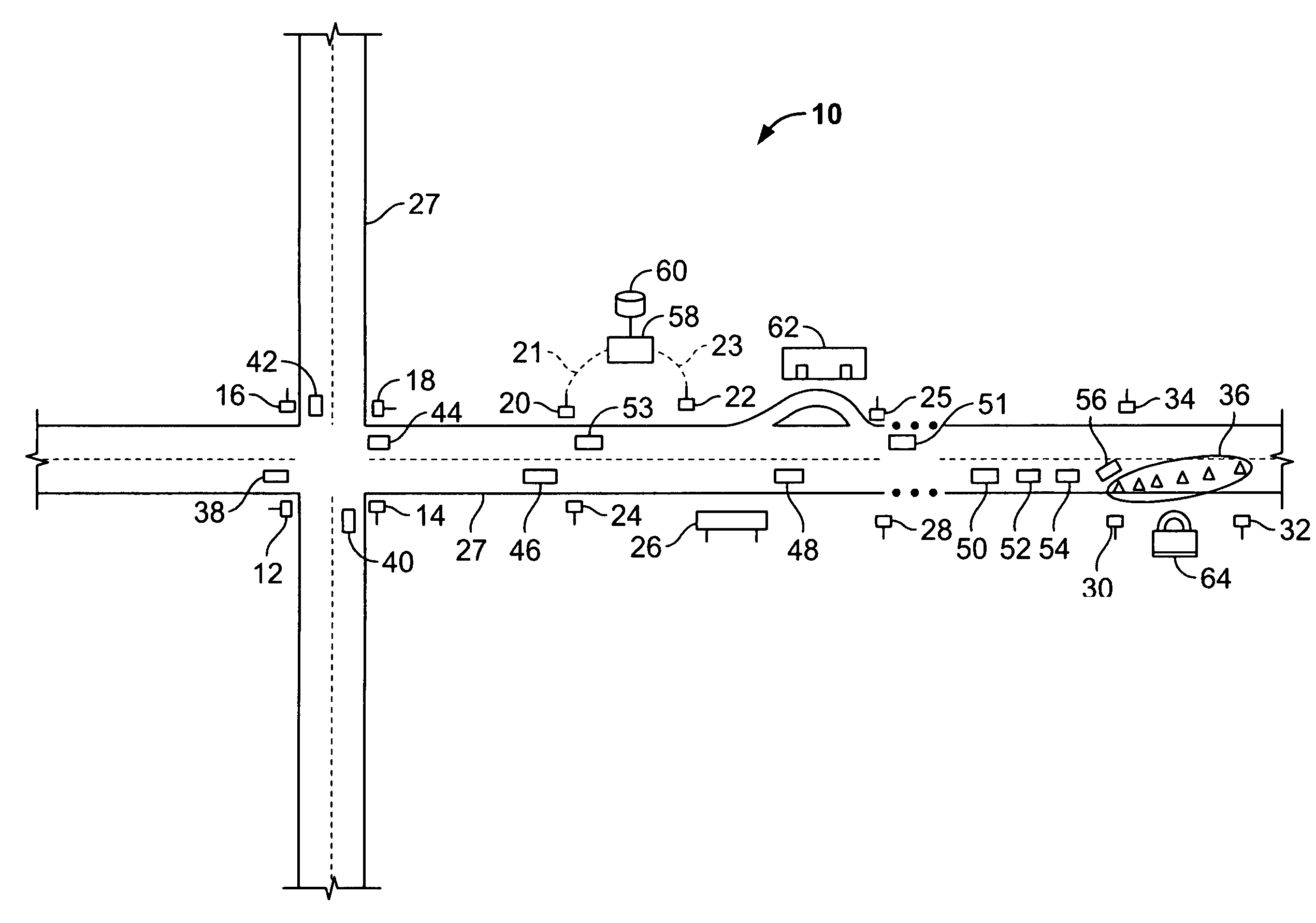
[0014]FIG. 1 illustrates an exemplary embodiment of a wireless traffic control system 10 providing wireless communication of information between a plurality of traffic control signs. The wireless traffic control system 10 generally includes a plurality of traffic control signs configured to wirelessly communicate information therebetween. For example, as shown in FIG. 1, traffic control signs 12, 14, 16, 18, 20, 22, 24, 25, 26, 28, 30, 32 and 34, and hazard zone artifacts 36 (e.g., traffic cones) together form a wireless network for communicating information between the traffic control signs and hazard zone artifacts. In operation, traffic control signs 12, 14, 16, 18, 20, 22, 24, 25, 26, 28, 30, 32 and 34, and hazard zone artifacts 36 may wirelessly transmit and receive vehicle information and / or traffic control information between each other, which may include information about the vehicles on the roadway 27 that is received from the vehicles as described in more detail herein.

[00...


PUM


Abstract

A wireless traffic control system and method for wirelessly communicating information using traffic control signs are provided. The method includes wirelessly transmitting at least one of traffic control information and vehicle information from a traffic control sign and wirelessly receiving the information transmitted from the traffic control sign by at least one other traffic control sign.

Description

CROSS REFERENCE TO RELATED APPLICATIONS[0001]This application is a continuation-in-part of and claims priority to copending non-provisional U.S. Patent Application entitled “System and Method to Wirelessly Communicate Information Between Traffic Control Signs and Vehicles,” assigned Ser. No. 10 / 869,411, and filed Jun. 16, 2004, which is hereby incorporated by reference in its entirety.BACKGROUND OF THE INVENTION[0002]This invention relates generally to traffic control systems, and more particularly, to traffic control systems providing wireless communication of information between a plurality of traffic control signs.[0003]Drivers traversing roadways in their vehicles are provided with many different traffic control signs having traffic control information, such as, for example, sign-directed cautions, alerts and information. This traffic control information is typically provided along and above the roadway to control traffic, as well as display other useful information (e.g., next ...

Claims


Application Information

Patent Timeline
Patent Type & Authority Patents(United States)
IPC IPC(8): G08B1/00G08B1/08G08G1/09G08G1/095
CPCG08G1/01G08G1/0104G08G1/0962G08G1/164G08G1/096758G08G1/096783G08G1/096791G08G1/096716
Inventor DIPIAZZA, GERALD CHARLES
Owner ARRIVER SOFTWARE LLC (N D GES D STAATES DELAWARE)
Learn More