
Deck board fastener with concave prongs

a technology of concave prongs and fasteners, which is applied in the direction of nails, walls, mechanical equipment, etc., can solve the problems of unsightly display of protruding fasteners and/or other components, time-consuming, expensive, and sometimes impossible procedures, and achieves the effect of reducing the amount of screw head protruding and close positioning of adjoining boards

Active Publication Date: 2008-07-15
OMG INC
View PDF58 Cites 80 Cited by
  • Summary
  • Abstract
  • Description
  • Claims
  • Application Information

AI Technical Summary

Benefits of technology

The solution provides a secure, easy-to-install deck fastening system that hides fasteners, prevents board separation, and reduces damage from thermal expansion, resulting in a stable and aesthetically pleasing deck surface.

Problems solved by technology

However, some of these deck-fastening systems require securing devices that are difficult to install or require extensive preparation.
Other deck fastening systems must be installed from below the deck, a time consuming, expensive, and sometimes impossible procedure.
Therefore, the display of protruding fasteners and / or other components is unsightly and possibly dangerous.
Since deck boards are subject to warping, splitting and shrinking, some of the known deck fastener systems do not prevent the deck boards from separating from the support joists over time.
The fasteners also can come loose or become out of position on the joists.
The separating of the boards from the joists may allow the boards to protrude above the deck surface, making the deck unsightly and less usable.
However, wide prongs have been found to have a tendency to split the deck board material, especially when the deck board material is a composite material.
In addition, thermal expansion and contraction of the boards has caused damage to the deck boards, the support member and / or the deck fastener.

Method used


Image

  • Deck board fastener with concave prongs
  • Deck board fastener with concave prongs
  • Deck board fastener with concave prongs

Examples


Embodiment Construction

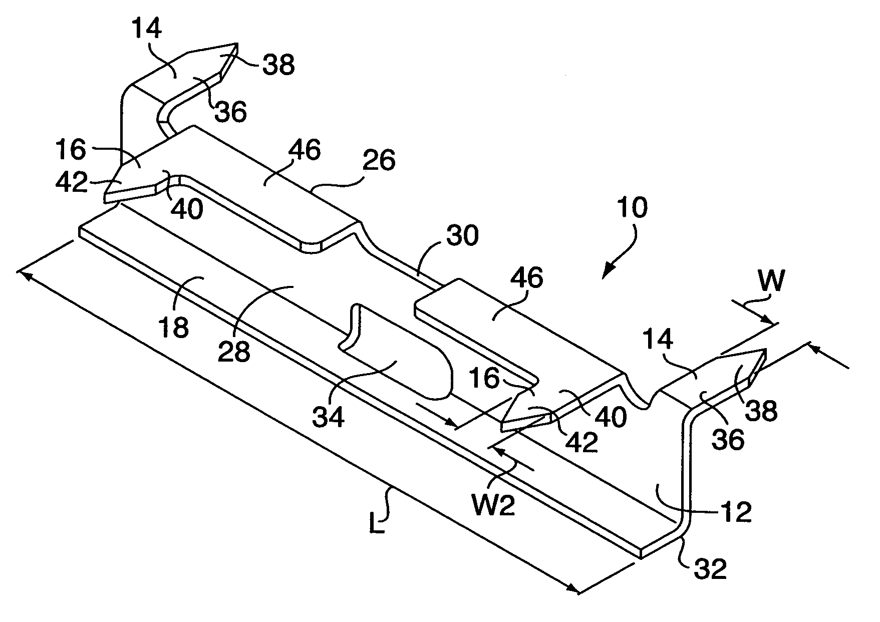
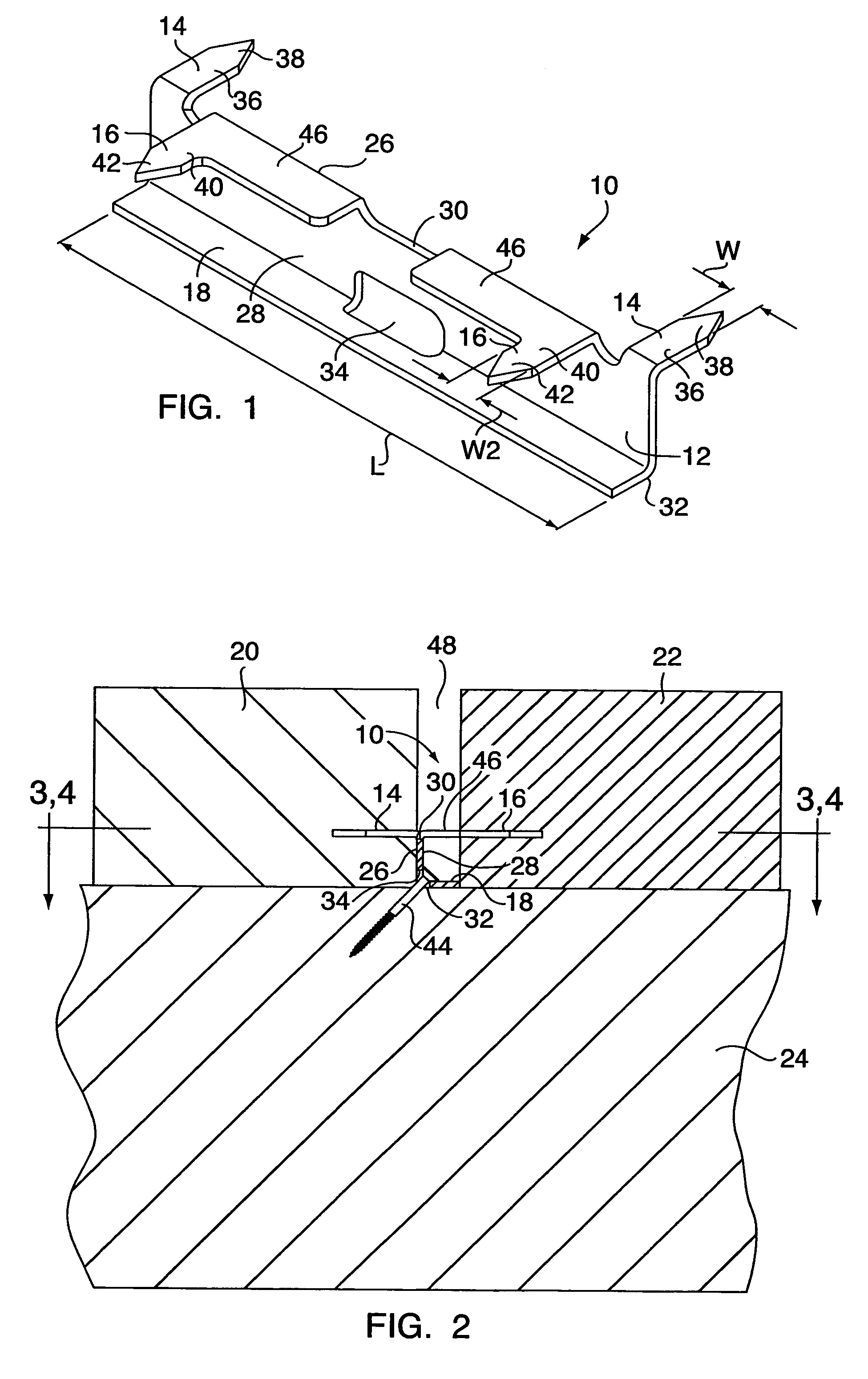
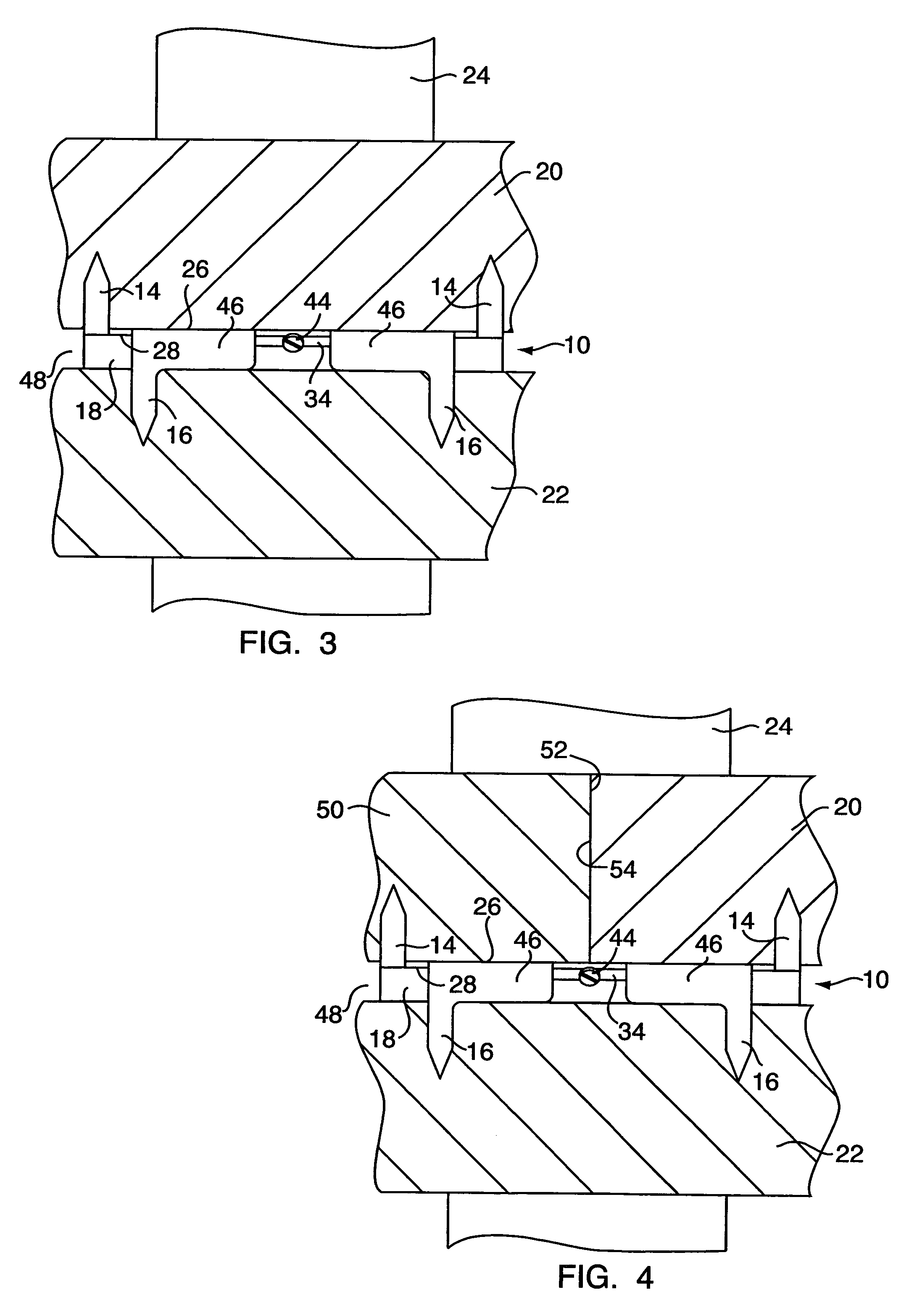
[0019]Referring to FIGS. 1 and 2, the fastener 10 of the present invention includes a thin, flat body portion 12, at least one first prong 14, at least one second prong 16, and a flange 18. The fastener 10 is operable to secure a first deck board 20 and a second deck board 22 together and to a support member 24.

[0020]Preferably, the fastener 10 is made of any suitable type of cut and bent sheet metal. In some embodiments, the fastener 10 is made from 0.06″ half-hardened steel that is rolled and not heat-treated. In other embodiments, the fastener 10 is made from 0.06″ 304 stainless steel that is quarter roll-hardened. The fastener may also be made from 0.03″ 420 or 440 stainless steel. Other materials and gauges are possible. Preferably, the fastener 10 is coated in order to hide the body portion 12 in the shadows created in the gap (discussed below and identified in FIG. 2 as “48”) between the adjoining deck boards 20, 22. In some embodiments, the fastener 10 is coated in a black o...


PUM


Abstract

According to the present invention, a fastener for securing a first board to an underlying supporting member and to at least one other board running adjacent and parallel to the first board. The fastener includes a body portion, first and second prongs, and a flange. The first prong extends outwardly from the body portion for driving into a first board. The second prong extends outwardly from the body portion for penetrating a second board. The body portion of the fastener includes an opening for receiving a connector. When installed, the connector passes through the opening in the body portion and into the supporting member, which supports and underlies the first and second boards. The flange extends outwardly from the body portion in order to maintain a desired gap between the first and second boards. The prongs may have concave insertion ends as defined by two spaced-apart insertion points.

Description

[0001]This is a continuation-in-part of U.S. patent application Ser. No. 10 / 844,246, filed May 12, 2004 now abandoned.FIELD OF THE INVENTION[0002]The invention concerns a deck fastener for securing deck boards together and to a supporting member, and deals more particularly with a deck fastener that does not protrude from the deck surface.BACKGROUND OF THE INVENTION[0003]Brackets, clips, and anchors for securing boards to joists without nail or screw heads protruding from the deck surface are known. However, some of these deck-fastening systems require securing devices that are difficult to install or require extensive preparation. For example, some deck fastening systems require pre-installing tracks on joists, pre-drilling slots or holes in boards for fasteners, or gluing the boards to the joists. Other deck fastening systems must be installed from below the deck, a time consuming, expensive, and sometimes impossible procedure.[0004]While these deck-fastening systems are designed ...

Claims


Application Information

Patent Timeline
Patent Type & Authority Patents(United States)
IPC IPC(8): E04B2/30E04B1/38E04C1/40E04C5/00F16B15/00E04B1/61E04B5/12E04C2/38E04H7/00F16B5/00
CPCE04B5/12F16B15/0038E04F2201/05F16B2015/0076F16B5/0008
Inventor MARTEL, DAVID J.HARTMANN, DAVID YOUNG
Owner OMG INC
Learn More