Laser image display apparatus

a technology of image display and laser, which is applied in the direction of picture reproducers, picture reproducers using projection devices, instruments, etc., can solve the problems of reducing the image quality of an image due to irregularities, and reducing the accuracy of the imag

Inactive Publication Date: 2008-07-15
PANASONIC CORP
View PDF20 Cites 16 Cited by
  • Summary
  • Abstract
  • Description
  • Claims
  • Application Information

AI Technical Summary

Benefits of technology

[0014]In view thereof, an object of the present invention is to solve the problems, and provide a laser image display apparatus which can efficiently reduce an inherent speckle noise appearing in the case where a coherent light source such as a laser source and the like is used, and realizes a bright and high-quality image having no luminosity irregularity.
[0016]With this construction, a ray of light emitted from the laser light source is irradiated to the light diffuser from the illumination optical system. Light diffusing elements are enclosed in the light diffuser, and the ray of light irradiated from the illumination optical system is diffused by the light diffusing elements. At this time, the light diffusing elements are moved, swayed or oscillated so that a phase pattern of the diffused rays of light changes instantly, and thereby a speckle pattern also changes. In other words, since different speckle patterns occur at each moment and these speckle patterns are timely averaged out at the time when an image projected to a particular plane via a spatial light modulator and a projection lens is observed, a high-quality two-dimensional image having a suppressed speckle noise can be obtained.
[0017]Further, divergence of the incident ray of light irradiated from the illumination optical system to the light diffuser is expressed by θ / 2+Sin−1(NA) if it is assumed that a numerical aperture of the illumination optical system is NA and a full angle of a light diffusing angle of the light diffuser is θ. Accordingly, if a distance between the light diffuser and the spatial light modulator is L, divergence of the ray of light on the spatial light modulator can be expressed by 2×tan(θ / 2+Sin−1(NA))×L. If the divergence is larger than a pitch P of a transmittance irregularity (luminous irregularity of a transmitted light ray) generated in the light diffuser, rays of light forming irregularity adjacent to each other are diffused and overlap with each other. Consequently, lowering of an image quality due to an irregularity can be suppressed.

Problems solved by technology

However, such display has a problem of the so-called speckle noise which is likely to occur due to use of a laser light source having high coherency.
Further, as described in Patent Document 4, the speckle noise can be reduced also by using a mobile diffuser, but there is a problem of noises such as motor driving sounds generated at the time when the diffuser is operated.
However, in the case of using the speckle reducing method disclosed in Patent Document 5, the light rays diffused in the diffuser optical system are more likely to partially come outside of an image display area of the spatial light modulator as the distance between the spatial light modulator and the diffuser optical system becomes longer.
As a result, the loss in the light intensity becomes larger, and the brightness of the screen lowers.
Therefore, as the distance between the diffuser optical system and the spatial light modulator comes closer, this deviated distribution of transmittance efficiency causes localization (luminosity irregularity) of light intensity on the spatial light modulator.
In other words, speckle noise prevention optical systems, typically diffuser optical systems using microparticles, cannot eliminate the speckle noise and realize a high-resolution, bright image having no luminosity irregularity if the optical system is not set in an appropriate position with respect to the spatial light modulator.

Method used


Image

  • Laser image display apparatus
  • Laser image display apparatus
  • Laser image display apparatus

Examples


embodiment 1

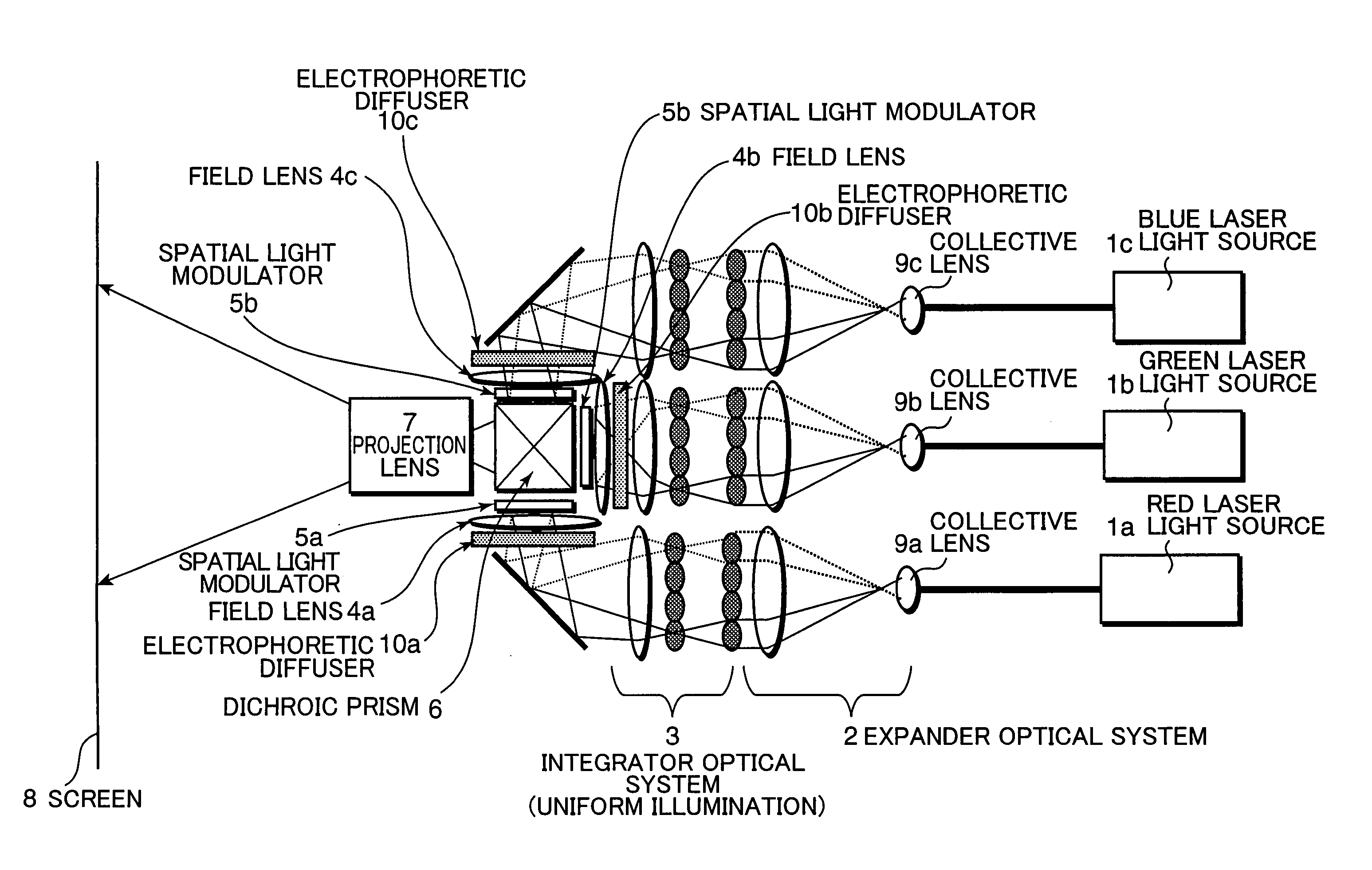
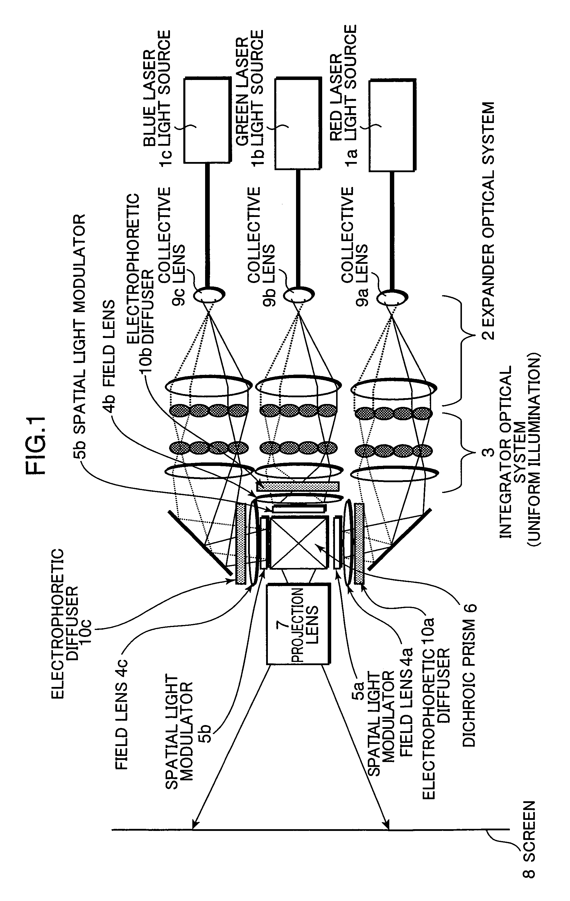
[0026]FIG. 1 shows a schematic diagram of a laser image display apparatus according to an embodiment of the present invention. Rays of light emitted from a red laser light source 1a, a green laser light source 1b, and a blue laser light source 1c are collected by collective lens 9a, 9b and 9c respectively. The collected rays of light are irradiated to electrophoretic diffusers (light diffusers) 10a, 10b, 10c respectively after being passed through an expander optical system 2 and an integrator optical system (illumination optical system) 3 and are beam-shaped to have a uniform light intensity distribution. The rays of light irradiated to the electrophoretic diffusers 10a, 10b, 10c are diffused by diffusing elements contained. therein. Consequently, directions of the rays of light after being passed through the electrophoretic diffuser 10a, 10b, 10c are diffused.

[0027]The rays of laser light diffused by the electrophoretic diffusers 10a, 10b, 10c are irradiated to spatial light modul...

embodiment 2

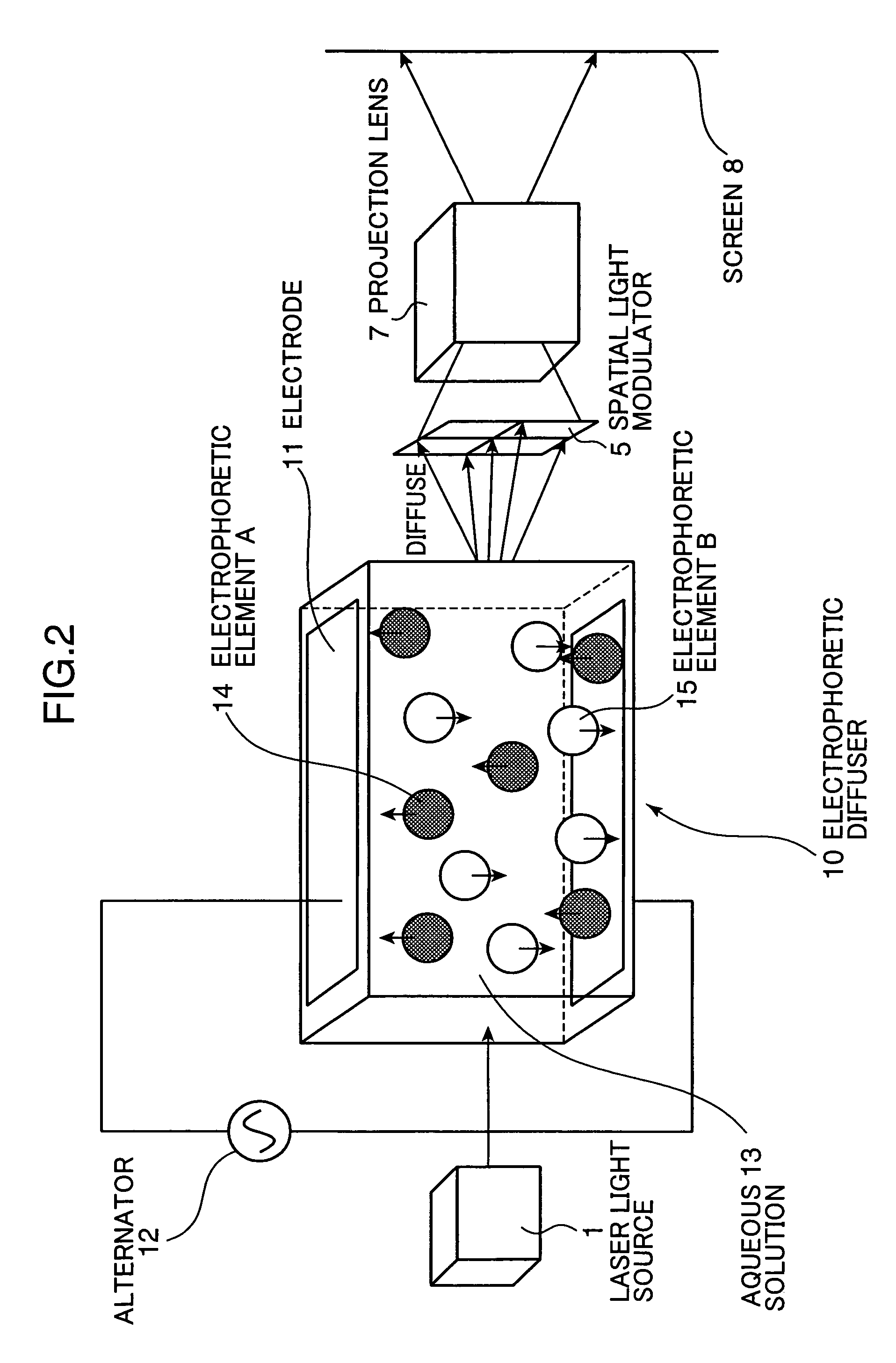
[0052]Further, according to another construction of a laser image display apparatus of the present invention, an electrophoretic diffuser 10 containing light diffusing elements is unified with a spatial light modulator 5 as shown in FIG. 4, and thereby a speckle noise is reduced and eliminated. Herein, the optical system such as the integrator optical system 3 and the like are omitted for simplicity. According to this construction, after the rays of light emitted from the light source having been passed through the expander optical system and the integrator optical system, rays of the light beam can be irradiated to the unified optical system including the electrophoretic diffuser 10 and the spatial light modulator 5 in a state of a uniform illumination light ray. Furthermore, as shown in FIG. 5, it can also be constructed so as to have a reflective spatial light modulator as a spatial light modulator. Here, LCOS (Liquid Crystal On Silicon), which is representative of all other refl...

embodiment 3

[0053]Further, according to another construction of a laser image display apparatus of the present invention, as shown in FIG. 6, a light diffuser containing light diffusing elements and a liquid crystal used in a two-dimensional spatial light modulator for projecting an image are contained in the same liquid. For example, it functions as a diffuser by moving the particles by heat, and, on the other hand, it functions as a two-dimensional light modulator by controlling a liquid crystal (a reflective liquid crystal is used in FIG. 6) by electricity.

[0054]Here, the same as in the embodiment 1, a distance between the diffuser and the light modulator needs to be set in an appropriate position to suppress the light amount loss and the luminosity irregularity to a minimum. Therefore, portions of a light diffusing function and a light modulating function needs to be separated, and the particles and the liquid crystal contained in the same liquid needs to be arranged in an appropriate posit...


PUM

PropertyMeasurementUnit
particle diameteraaaaaaaaaa
light diffusing angleaaaaaaaaaa

Abstract

A light diffuser containing light diffusing elements is arranged in the most appropriate position between a spatial light modulator and an illumination optical system. Thereby, particles as light diffusing elements diffuse rays of light emitted from a laser light source. Accordingly, indefinite numbers of speckle pattern are formed so that, for example, a speckle noise which occurs on an image projected to a screen is reduced. As a result, loss of light amount after light diffusion is suppressed to small amount, and thereby a laser image display apparatus capable of displaying a bright and high-quality image having no luminosity irregularity is provided.

Description

TECHNICAL FIELD[0001]The present invention relates to an image display apparatus using a laser as a light source. More particularly, it pertains to a laser image display apparatus comprising means for reducing speckle noises which appears on a display.BACKGROUND ART[0002]FIG. 7 shows a schematic construction of a conventional laser display. At first, rays of light emitted from laser light sources 101a-101c including three RGB colors (R: red, G: green, B: blue) are beam-expanded by an expander optical system 102 including collective lens 109a-109c. Next, expanded light rays are beam-formed by an integrator optical system including lenses and arrays of small lenses to provide a uniform illumination to a spatial light modulator 105. Herein, field lenses 104a-104c are adapted for converting the rays of light having been passed through the spatial light modulators 105a-105c into collected or collected light rays so as to make rays of light pass through an aperture of a projection lens 10...

Claims


Application Information

Patent Timeline
Patent Type & Authority Patents(United States)
IPC IPC(8): G03B21/14G02F1/13G03B21/00H04N9/31
CPCH04N9/3129
Inventor MORIKAWA, AKIHIROKASAZUMI, KEN'ICHIMIZUUCHI, KIMINORI
Owner PANASONIC CORP
Why Eureka
Try Eureka