Air driven diaphragm pump

a diaphragm pump and air drive technology, which is applied in the direction of positive displacement liquid engines, flexible wall reciprocating engines, positive displacement engines, etc., can solve the problems of reducing the pumping capacity, and exposing the apparatus, so as to increase the resulting pumping capacity and increase the pressure capacity

Active Publication Date: 2008-07-15
PSG CALIFORNIA LLC
View PDF22 Cites 38 Cited by
  • Summary
  • Abstract
  • Description
  • Claims
  • Application Information

AI Technical Summary

Benefits of technology

[0006]The present invention is directed to an air driven double diaphragm pump which employs a converted pump chamber for increasing the resulting pumping capacity above that provided by a supply of air pressure behind a single diaphragm. The pump includes a shaft extending through the air valve and affixed at its ends to the two diaphragms in a double diaphragm pump. The shaft includes a passage in communication with the air chamber adjacent to the pump chamber and with the pump chamber converted to an air chamber.
[0007]Thus, it is an object of the present invention to provide an improved diaphragm pump of increased pressure capacity. Other and further objects and advantages will appear hereinafter.

Problems solved by technology

An air valve controls flow to alternate air pressure and exhaust to and from each of the air chambers, resulting in reciprocation of the pump.
The aforementioned systems provide a pumping capacity which is limited to the pressure of the supply air behind each diaphragm.
Such apparatus are exposed and vulnerable.

Method used


Image

  • Air driven diaphragm pump
  • Air driven diaphragm pump

Examples


Embodiment Construction

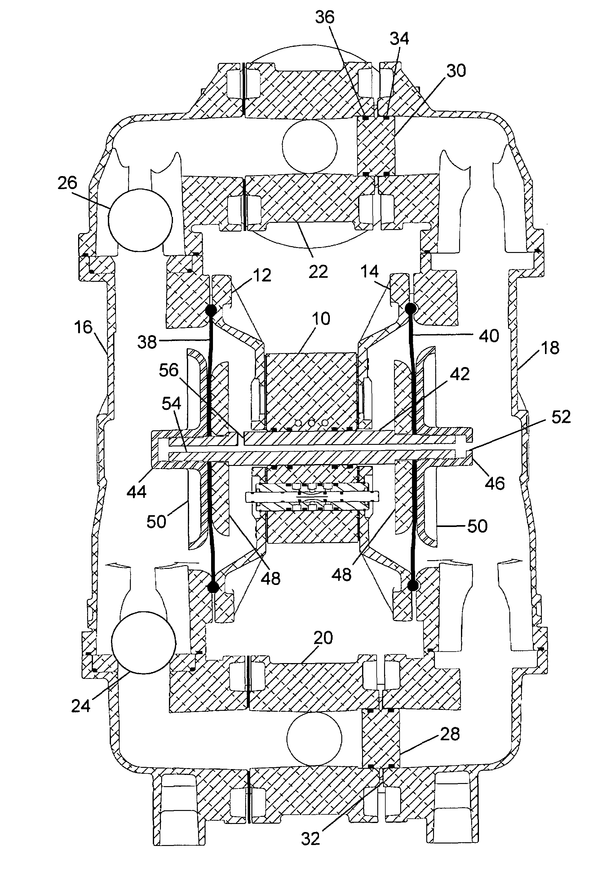
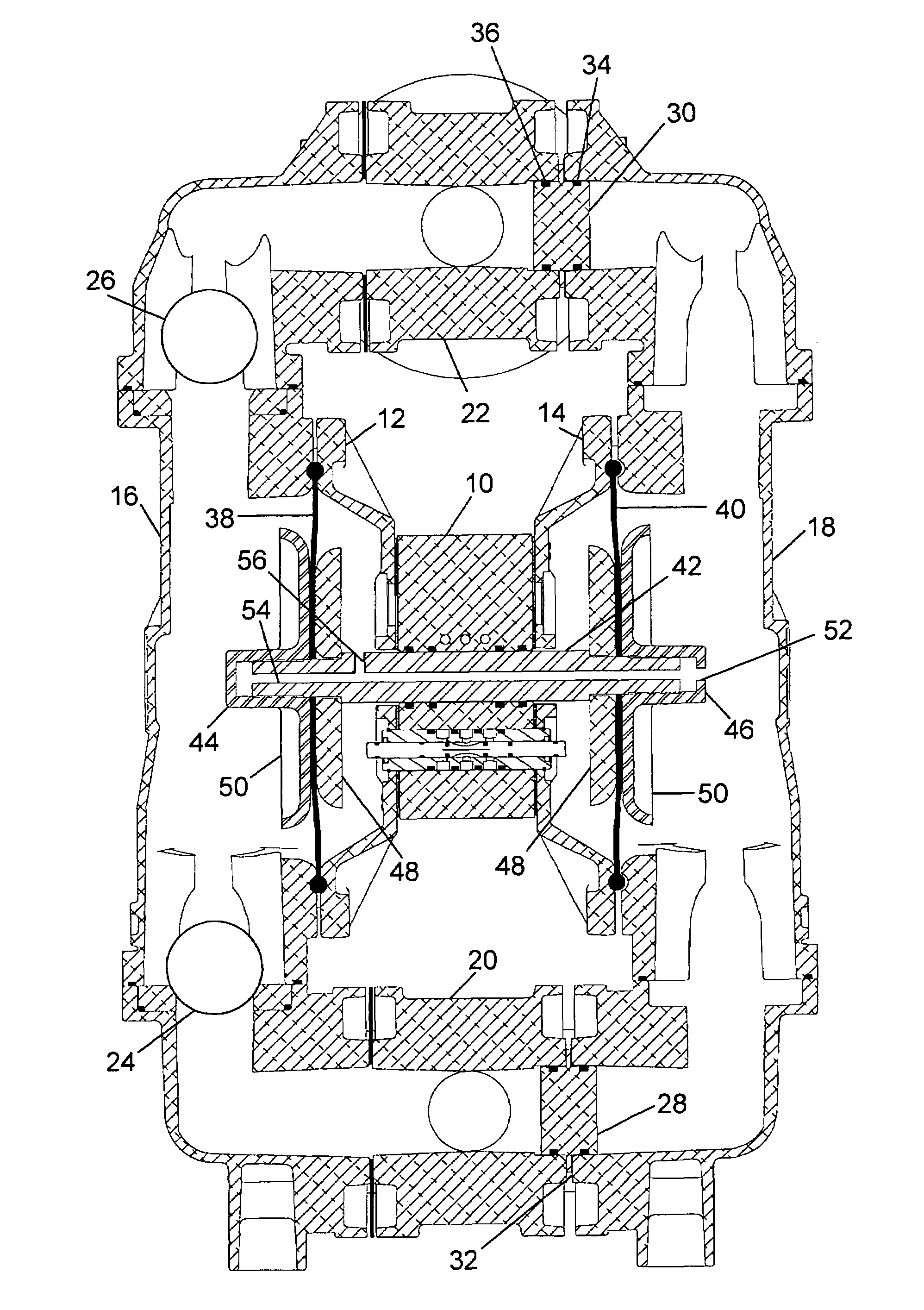
[0009]The preferred embodiment includes a double diaphragm pump such as disclosed in U.S. Pat. No. 5,957,670, the disclosure of which is incorporated herein by reference. The preferred embodiment further includes an air valve as disclosed in U.S. Published Application No. 2005 / 0249612, the disclosure of which is incorporated herein by reference.

[0010]Briefly, the pump includes an air valve 10 positioned between a first air chamber housing 12 and a second air chamber housing 14. The air chamber housings 12 and 14 extend in opposite directions to either side of the air valve 10 to define air chambers which receive pressurized air for reciprocating the pump. Pump chamber housings 16 and 18 are bolted through circular flanges defined by the air chamber housings 12 and 14 and the pump chamber housings 16 and 18 in a conventional manner outwardly of the air chamber housings 12 and 14. Inlet manifold 20 and outlet manifold 22 provide conventional supply and discharge systems along with int...


PUM


Abstract

An air driven diaphragm pump includes two diaphragms affixed to a common shaft. The shaft extends through an air valve providing reciprocating pressurized air to the diaphragms through associated air chambers. A pump chamber with intake and exhaust valves is associated with one of the two diaphragms while a further air chamber replaces a pump chamber and is associated with the other of the diaphragms. A passage extends through the shaft and is in communication with the air chamber adjacent to the pump chamber and with the further air chamber converted from the pump chamber.

Description

BACKGROUND OF THE INVENTION[0001]The field of the present invention is air driven double diaphragm pumps employed in high pressure configurations.[0002]Air driven double diaphragm pumps employ a source of pressurized air for operation and are quite versatile in their ability to pump a wide variety of material. Pumps having double diaphragms driven by compressed air directed through an actuator valve are found in U.S. Pat. Nos. 5,957,670; 5,169,296; 4,247,264; Des. 294,946; Des. 294,947; and Des. 275,858. Actuator valves used in such pumps are illustrated in U.S. Published Application No. 2005 / 0249612; and U.S. Pat. No. 4,549,467. The disclosures of the foregoing patents and published application are incorporated herein by reference.[0003]Common to many air driven diaphragm pumps and as shown in the aforementioned patent publications relating to air driven diaphragm pumps is the presence of an actuator housing having air chambers facing outwardly to cooperate with two pump diaphragms...

Claims


Application Information

Patent Timeline
Patent Type & Authority Patents(United States)
IPC IPC(8): F04B43/14F01B19/02
CPCF04B43/0736
Inventor EBERWEIN, DENNIS D.
Owner PSG CALIFORNIA LLC
Why Eureka
Try Eureka