Operating room magnifier

a magnifying device and operating room technology, applied in the field of magnifiers, can solve the problems of increasing the length of such procedures, difficult to distinguish with the naked eye, and increasing the difficulty of surgeons' jobs, and achieve the effect of easy replacement and easy replacemen

Active Publication Date: 2008-07-15
WELCH GRACIE L
View PDF26 Cites 15 Cited by
  • Summary
  • Abstract
  • Description
  • Claims
  • Application Information

AI Technical Summary

Benefits of technology

[0007]In accordance with another aspect of the invention, there is provided an operating room magnifier. The magnifier comprises a base for supporting the magnifier, a lens holder, and a neck for mechanically connecting the lens holder to the base. A lens is held by the lens holder. The lens holder is adapted to hold a light and to direct a light beam from the light to an area under the lens to illuminate an object being viewed through the lens. The magnifier is autoclave compatible for sterilization. Further, the lens is easily removable and replaceable for sterilization separate from the lens holder.

Problems solved by technology

Such reconstruction procedures often require delicate manipulation of tissue and / or bone using very specialized and tools (e.g., microsurgical instruments) having very small working ends, which are difficult to distinguish with the naked eye.
The surgical technicians must be able to quickly and properly identify and handle these microsurgical tools throughout a procedure and failure to quickly and properly identify microsurgical tools may lengthen the procedure, make the surgeon's job more difficult, or degrade the results.
Unfortunately, increasing the length of such procedures may be a detriment to a patient's recovery or even place the patient's life at risk, for example when internal bleeding must be stopped.
In this instance, lights normally provided for viewing instruments are not available.
As a result, instrument selection is hampered by the difficulty in distinguishing specific instruments.
The low light level may also make selection of a medicine difficult.

Method used


Image

  • Operating room magnifier
  • Operating room magnifier
  • Operating room magnifier

Examples


Embodiment Construction

[0033]The following description is of the best mode presently contemplated for carrying out the invention. This description is not to be taken in a limiting sense, but is made merely for the purpose of describing one or more preferred embodiments of the invention. The scope of the invention should be determined with reference to the claims.

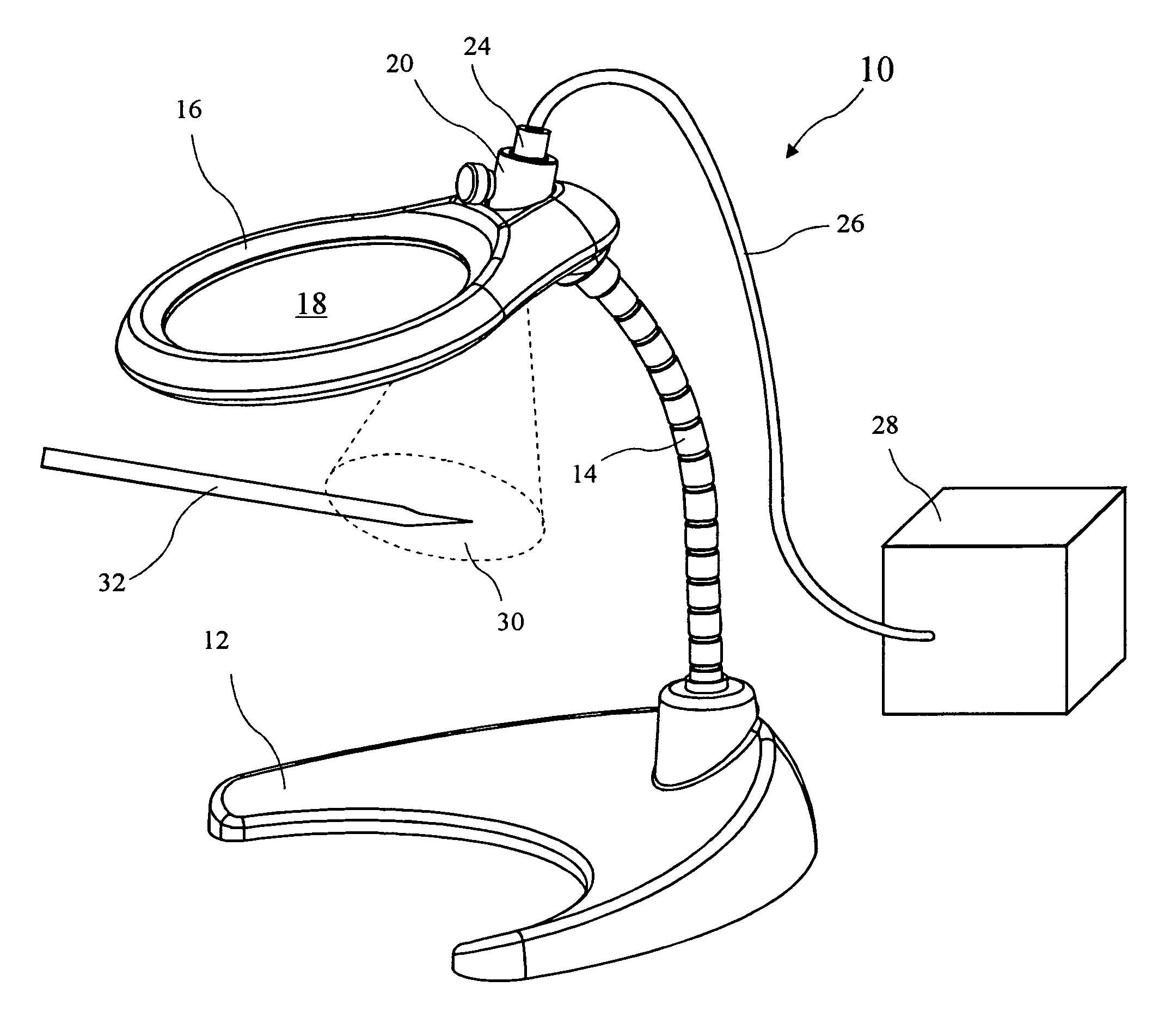
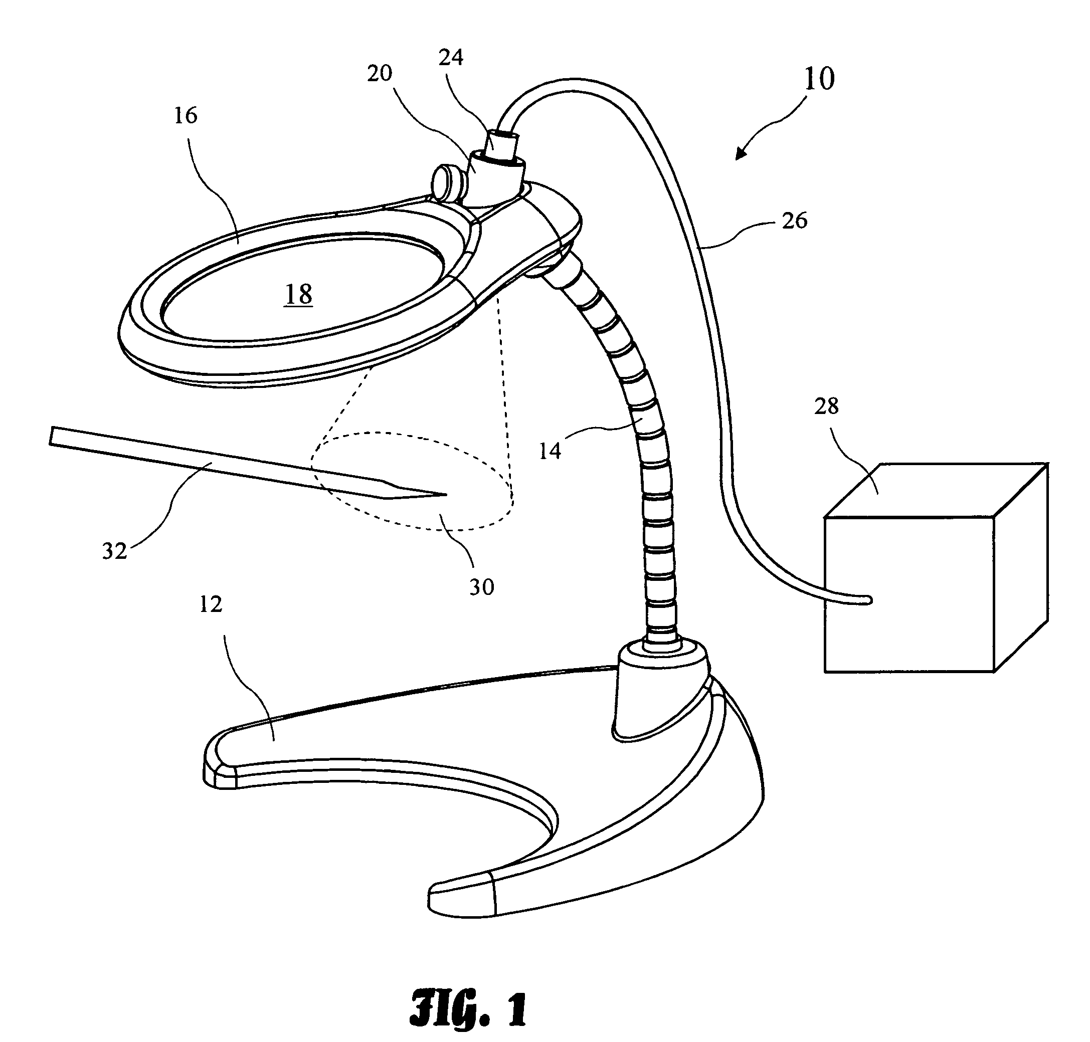
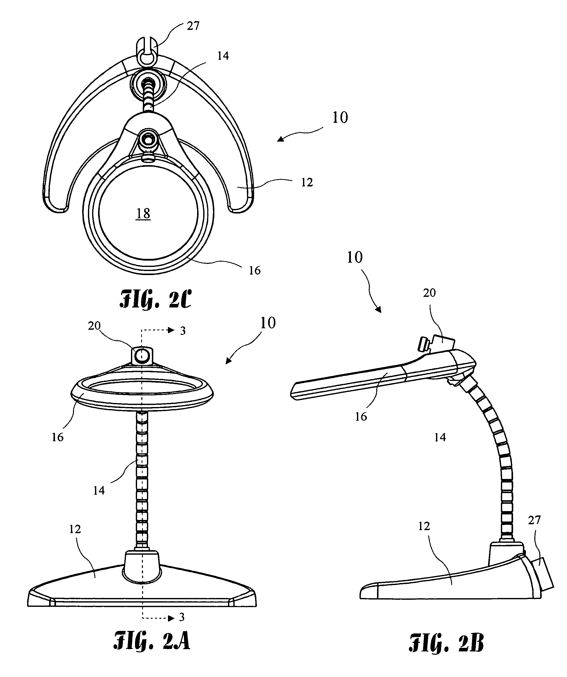
[0034]An operating room magnifier 10 according to the present invention is shown in FIG. 1. The magnifier 10 includes a base 12, a neck 14, and a lens holder 16. The neck 14 connects the lens holder 16 to the base 12. The lens holder 16 holds a lens 18 which allows magnification of an object 32, for example a microsurgical instrument, held under the lens 18.

[0035]Because some surgical procedures require a dark operating room, a light adapter 20 is provided to hold a light 24. The light adapter 20 is adapted to hold the light 24 and direct a light beam 30 from the light 24 to an area under the lens 18 to illuminate the object 32 being viewed throug...


PUM


Abstract

An operating room magnifier is adapted to utilize an operating room light source and may be sterilized to allow use on a sterile field. The magnifier comprises a base, a neck, and a lens frame. The lens frame holds a lens and receives a light connected to the light source, providing a light beam to an object held under the magnifying glass. The light source may be a known fiber optics light source commonly used in operating rooms, or a special dedicated light source. The magnifier is particularly useful in identifying microsurgical instruments.

Description

[0001]The present application claims the benefit of U.S. Provisional Application Ser. No. 60 / 567,373, filed May 1, 2004, which application is incorporated herein by reference.BACKGROUND OF THE INVENTION[0002]The present invention relates to magnifiers and in particular to a sterile magnifier for operating room use.[0003]Modern surgery often involves reconstruction of very small and detailed structures. Such reconstruction procedures often require delicate manipulation of tissue and / or bone using very specialized and tools (e.g., microsurgical instruments) having very small working ends, which are difficult to distinguish with the naked eye. Surgical technicians and others are required to properly identify multiple specific microsurgical instruments used during each step of such procedures. The surgical technicians must be able to quickly and properly identify and handle these microsurgical tools throughout a procedure and failure to quickly and properly identify microsurgical tools ...

Claims


Application Information

Patent Timeline
Patent Type & Authority Patents(United States)
IPC IPC(8): G02B27/02A61B19/00G02B21/00G02B25/02
CPCA61B19/52G02B25/02A61B2019/5219A61B2019/5206A61B90/36A61B2090/306A61B2090/3616
Inventor WELCH, GRACIE L.
Owner WELCH GRACIE L
Why Eureka
Try Eureka