
Powered toothbrush with associated oral solution dispenser mechanism

Inactive Publication Date: 2008-07-22
TYBINKOWSKI ANDREW P +2
View PDF3 Cites 42 Cited by
  • Summary
  • Abstract
  • Description
  • Claims
  • Application Information

AI Technical Summary

Benefits of technology

[0013]Another object of the present invention is to provide a solution dispensing toothbrush which is effective in operation, durable, attractive in appearance, and relatively inexpensive to manufacture.
[0014]Still another object of the present invention is to provide apparatus whereby a non-solution dispensing powered toothbrush can be quickly and easily upgraded into a dispensing powered toothbrush.SUMMARY OF THE INVENTION
[0015]These and other objects of the present invention are addressed by the provision and use of a novel solution dispenser mechanism which can be used with the handle of a conventional powered toothbrush, whereby to quickly and easily provide a solution-dispensing powered toothbrush.
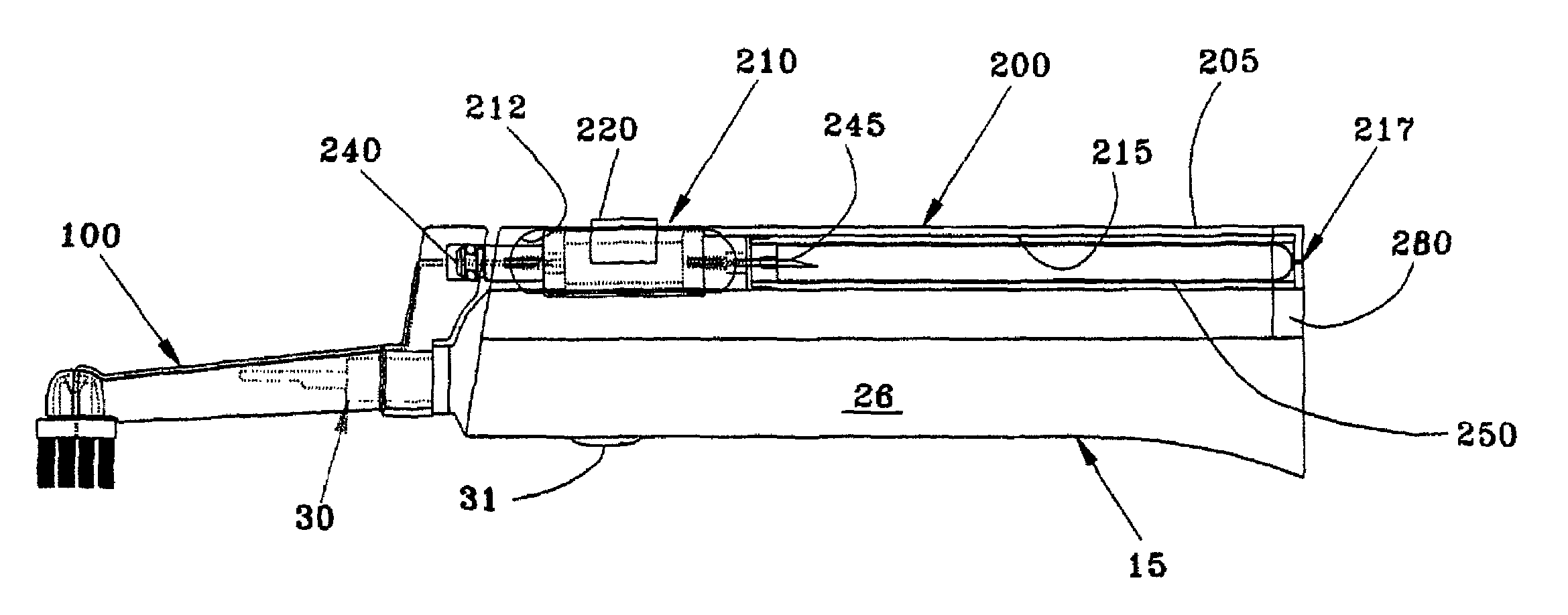
[0017]With the above objects in view, a feature of the invention is the provision of an oral solution dispenser apparatus for attachment to a powered toothbrush handle having a drive coupling mounted thereon. The apparatus comprises a housing adapted for attachment to the handle, the housing being adapted for receiving a cartridge containing the oral solution, a pump disposed on the housing for moving the oral solution from the cartridge, and an outlet nozzle mounted on the housing and adapted to permit movement of the oral solution from the pump and from the housing. A head having bristles thereon is adapted to interconnect with the handle drive coupling and the housing outlet nozzle, to facilitate powered movement of the bristles and movement of the oral solution from the outlet nozzle to proximate the bristles.

Problems solved by technology

In the past, there have been a number of proposals for achieving the foregoing, but all of these proposals are believed to suffer from one or more significant disadvantages, including ineffectiveness of operation, lack of durability, unattractiveness of appearance, prohibitive cost of manufacture, cross-contamination, etc.
In other words, none of these proposals is believed to have addressed the issue of how a non-dentifrice-dispensing powered toothbrush can be quickly and easily converted into a dentifrice-dispensing powered toothbrush.

Method used


Image

  • Powered toothbrush with associated oral solution dispenser mechanism
  • Powered toothbrush with associated oral solution dispenser mechanism
  • Powered toothbrush with associated oral solution dispenser mechanism

Examples


Embodiment Construction

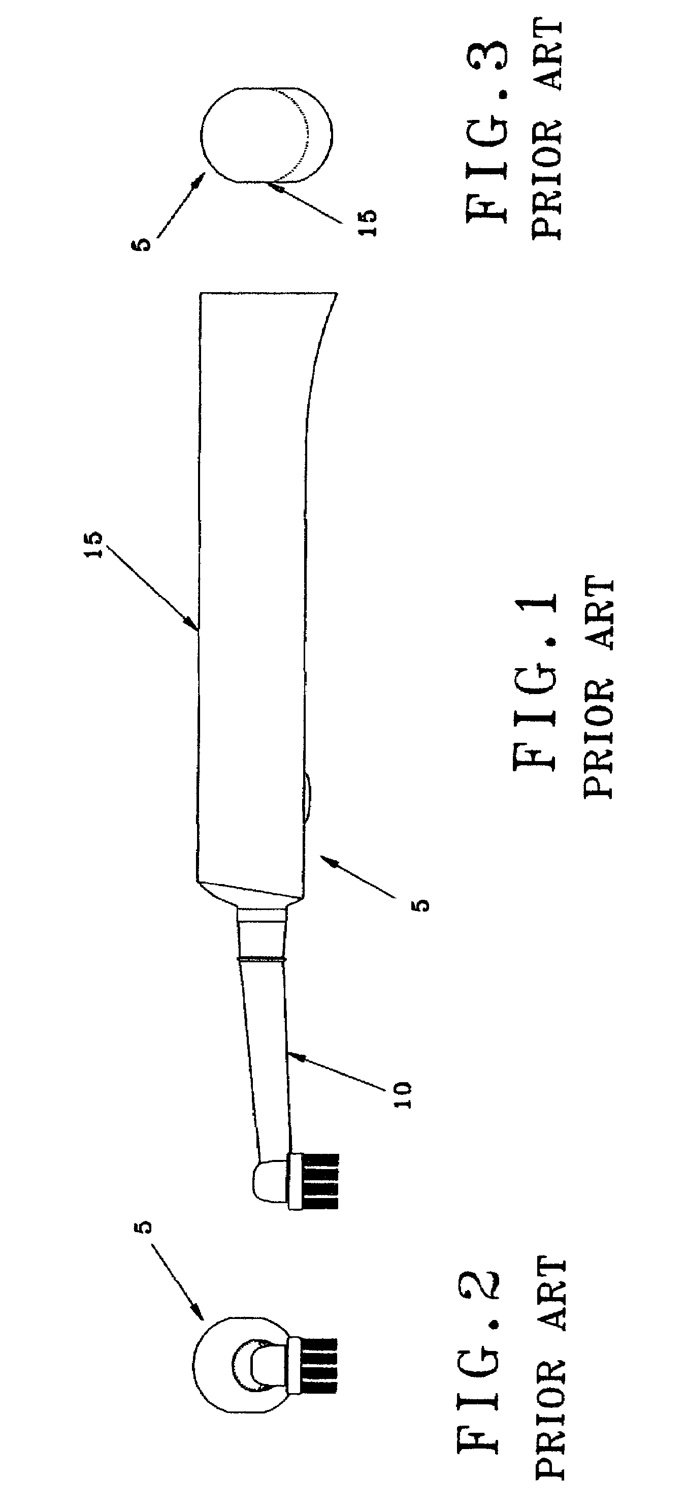
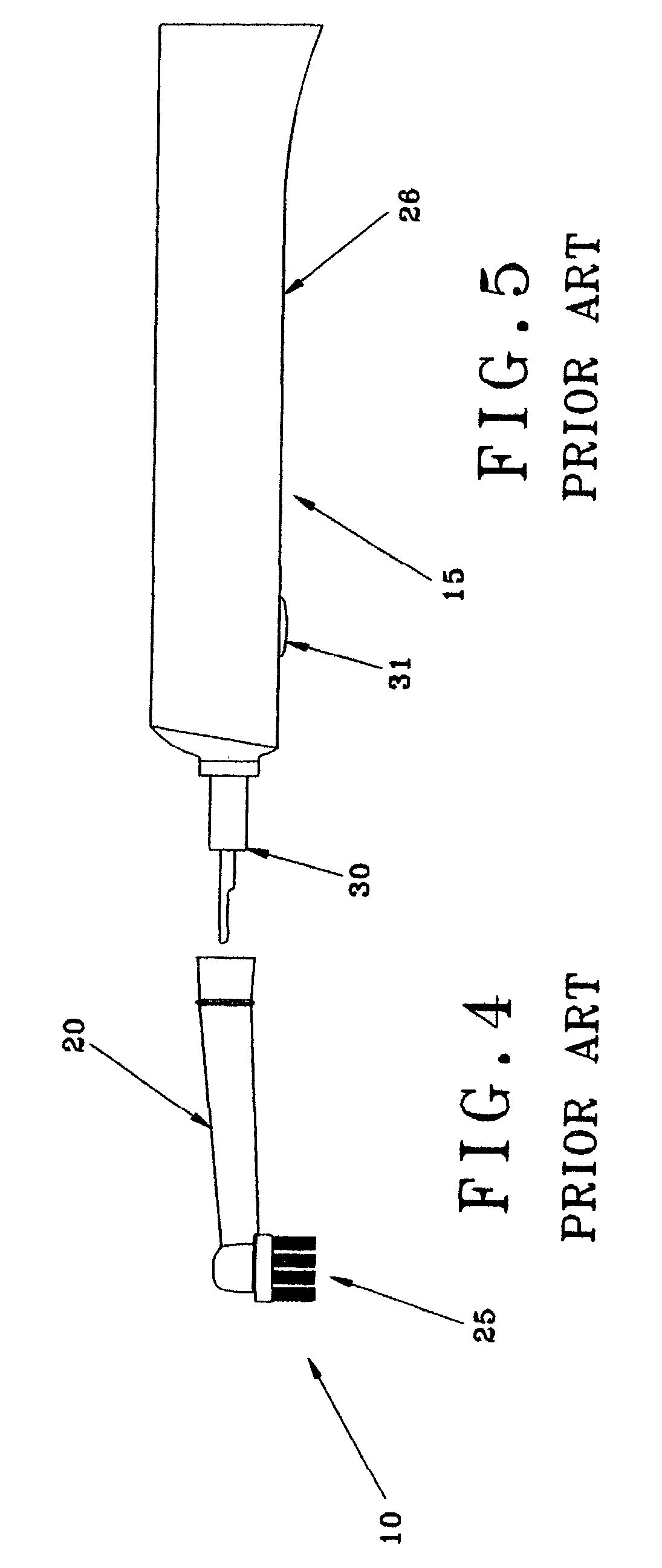
[0028]Looking first at FIGS. 1-5, there is shown a conventional powered toothbrush 5. Conventional powered toothbrush 5 generally comprises a replaceable head 10 and a handle 15. Replaceable head 10 (FIGS. 1, 2 and 4) generally comprises a stem 20 having a plurality of bristles 25 extending outwardly from a distal end thereof. Handle 15 (FIGS. 1, 3 and 5) has an elongated body 26 (FIG. 5) that includes a driver mechanism (not shown) located within the handle. This driver mechanism powers a drive coupling 30 (FIGS. 5 and 5A) extending out a distal end of handle body 26 whereby, when a replaceable head 10 is mounted on drive coupling 30 and the handle's driver mechanism is actuated, e.g., with button 31 (FIG. 5), the handle's driver mechanism can drive replaceable head 10 longitudinally and / or laterally and / or rotationally. Such driver mechanisms are of the sort well known in the art.

[0029]In accordance with the present invention, and looking now at FIGS. 6-10, there is provided a nov...


PUM


Abstract

An oral solution dispenser apparatus for attachment to a powered toothbrush handle having a drive coupling mounted thereon, includes a housing adapted for attachment to the handle, the housing having a recess therein for receiving a cartridge containing the oral solution, a pump disposed in the housing for moving the oral solution from the cartridge, and an outlet nozzle extending from the housing and adapted to permit movement of the oral solution from the pump and from the housing. A head having bristles thereon is adapted to interconnect with the handle drive coupling and the housing outlet nozzle, to facilitate powered movement of the bristles and movement of the oral solution from the outlet nozzle to proximate the bristles.

Description

REFERENCE TO PENDING PRIOR PATENT APPLICATIONS[0001]This patent application claims benefit of U.S. Provisional Patent Application Ser. No. 60 / 325,014, filed Sep. 26, 2001 by Andrew Tybinkowski et al. for POWERED TOOTHBRUSH WITH ASSOCIATED FLUID DISPENSER MECHANISM, which patent application is hereby incorporated herein by reference.FIELD OF THE INVENTION[0002]This invention relates to dental apparatus in general, and more particularly to toothbrushes.BACKGROUND OF THE INVENTION[0003]Toothbrushes are well known in the art. In general, a toothbrush comprises a head having a plurality of bristles extending therefrom, and a handle adapted to be grasped by the hand of a user.[0004]Powered toothbrushes are also well known in the art. In general, a powered toothbrush comprises a replaceable head having a plurality of bristles extending therefrom, and a handle adapted to be grasped by the hand of the user. The replaceable head is adapted to be removably mounted on the handle so that a drive...

Claims


Application Information

Patent Timeline
IPC IPC(8): A46B13/04A46B11/00A46B11/02A61C17/22A61C17/28A61C17/36
CPCA61C17/222A61C17/36A61C17/28A61C17/227
Inventor TYBINKOWSKI, ANDREW P.CASTELLUCCI, FEDERICOLUSTIG, L. PAUL
Owner TYBINKOWSKI ANDREW P
Learn More