Umbrella with a vented canopy deployable and retractible to a dihedral shape with a positively moved canopy and vent cover

a vent cover and umbrella technology, applied in tents/canopies, building types, constructions, etc., can solve problems such as substantial wind loads

Inactive Publication Date: 2008-07-22
CALDWELL JOHN W
View PDF4 Cites 22 Cited by
  • Summary
  • Abstract
  • Description
  • Claims
  • Application Information

AI Technical Summary

Benefits of technology

[0011]As a consequence this umbrella may be deployed conveniently, and can as conveniently be retracted, with the vent positively open at all deployed positions.

Problems solved by technology

Such structures are usually mounted on stands and are subject to substantial wind loads which might overturn them.

Method used


Image

  • Umbrella with a vented canopy deployable and retractible to a dihedral shape with a positively moved canopy and vent cover
  • Umbrella with a vented canopy deployable and retractible to a dihedral shape with a positively moved canopy and vent cover
  • Umbrella with a vented canopy deployable and retractible to a dihedral shape with a positively moved canopy and vent cover

Examples


Embodiment Construction

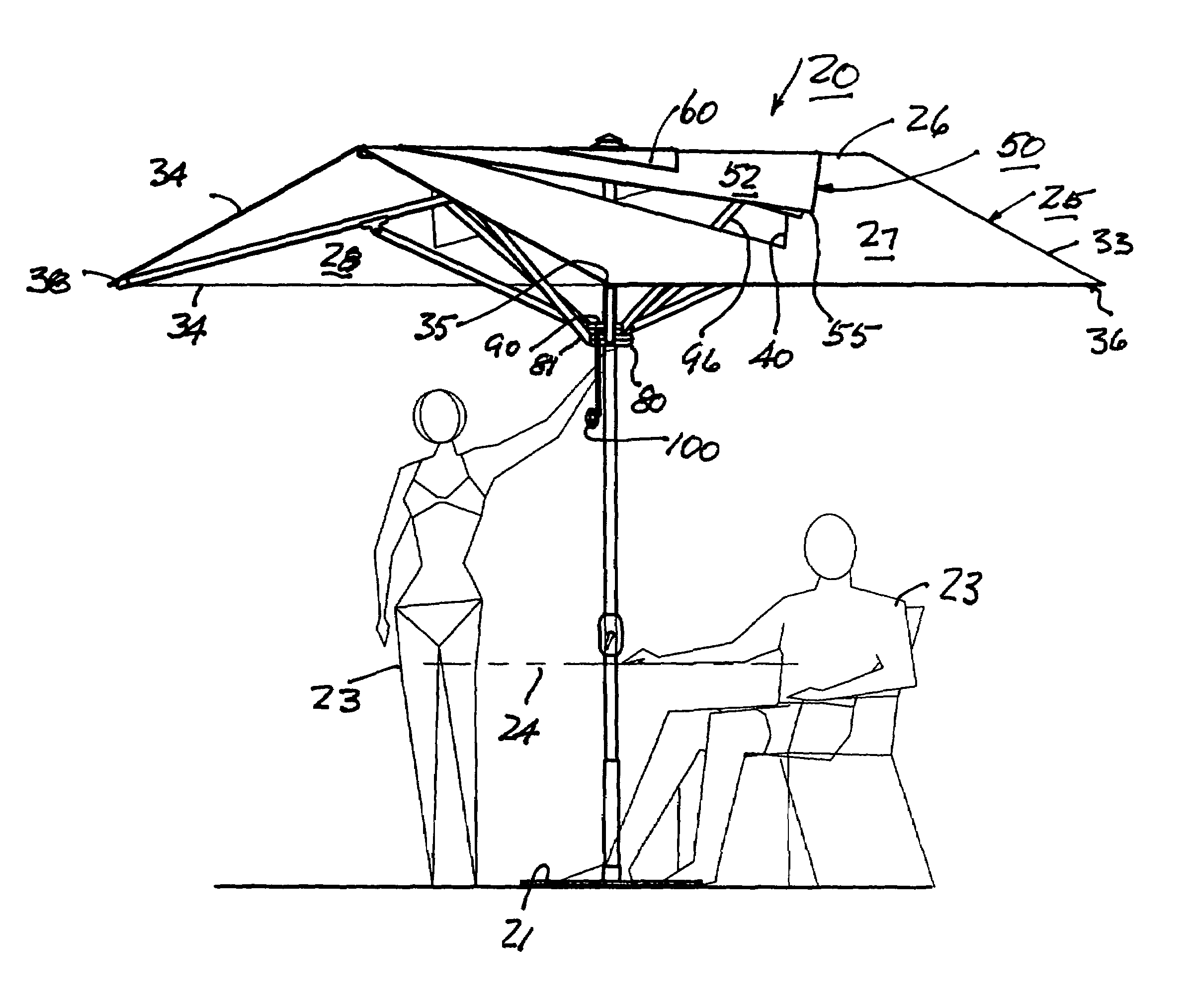
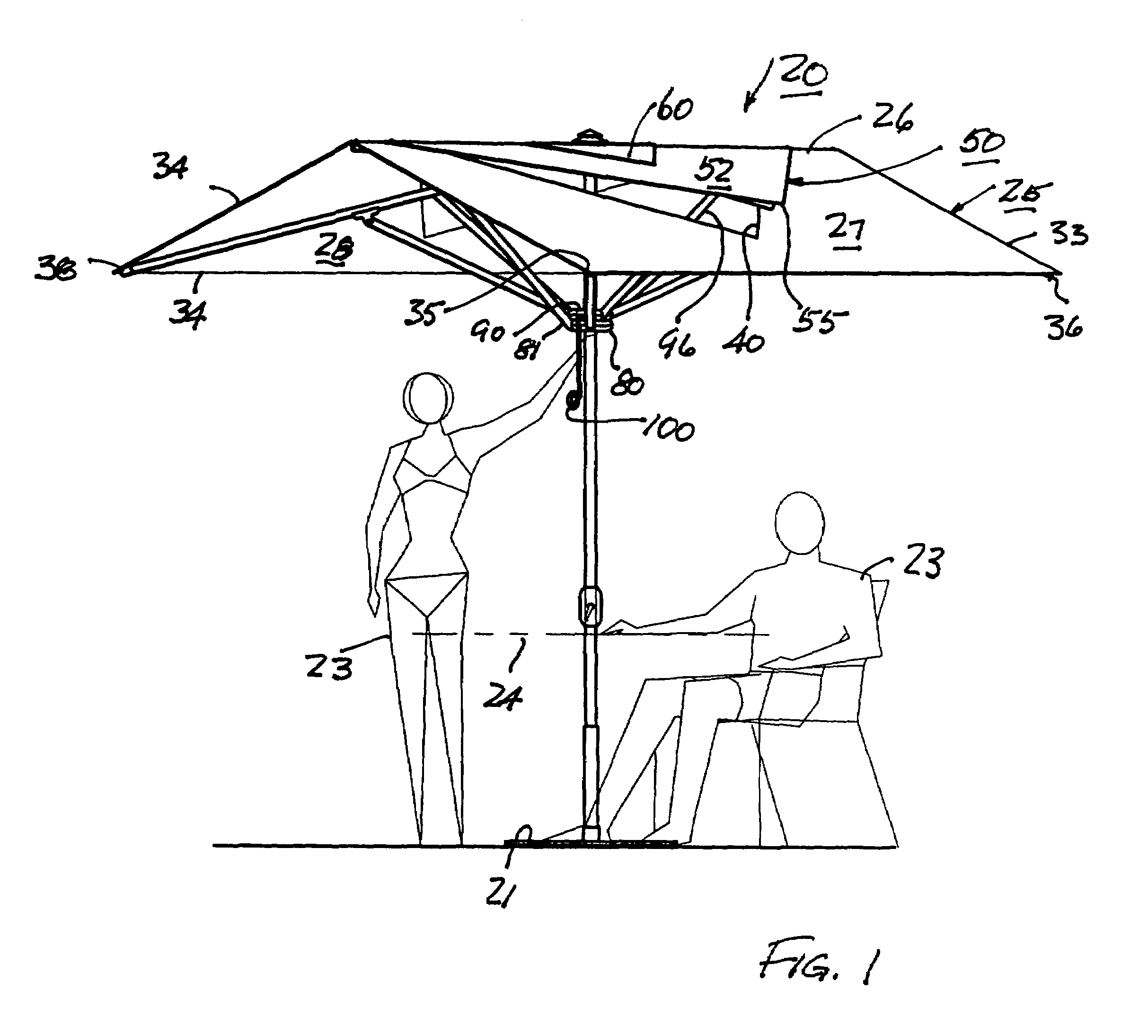
[0020]FIG. 1 shows the preferred embodiment of this invention in its most frequently deployed position. An umbrella 20 is mounted to a stand 21 to support a central pole 22 with the axis in an upright position. Instead of a stand, sockets or other types of support can as readily be used. Persons 23 and objects such as tables and chairs can conveniently be sheltered under the umbrella. A table 24 is suggested by a broken line in FIG. 1.

[0021]As shown in FIG. 1, the umbrella includes a canopy 25 which is preferably rectangular so that when deployed it will form a dihedral angle with a ridge 26 (more properly, an “edge” of a dihedral) with a pair of rectangular faces 27, 28. It is a feature of this invention that the dihedral angle between the faces can be adjusted, even to the extent that it is 180 degrees (a flat plane). More usually the dihedral will be on the value of about 120 degrees.

[0022]It is of interest that with this rectangular arrangement, a 9 foot by 9 foot square umbrell...


PUM


Abstract

An umbrella assembly providing a dihedral shelter atop a pole which can be deployed to different dihedral angles and retracted to a compact configuration. It further includes a vent port in a cavity which is overhung by a positively positioned vent port cover.

Description

FIELD OF THE INVENTION[0001]A foldable, retractable umbrella having a vented canopy deployable to a dihedral shape, and a vent cover overhanging the vent in the canopy, deployable to a dihedral strip, both by dedicated arms, the dihedral angle being adjustable.BACKGROUND OF THE INVENTION[0002]This invention is directed to larger umbrellas commonly used for shading in outdoor settings such as parties, pool sides, and outdoor dining areas. It is collapsible in the sense of being retractable for storage, and deployable to its working configurations.[0003]The working configuration of this invention is a dihedral canopy structure, folded along a dihedral edge. The dihedral angle is adjustable, and at one extreme may be 180 degrees (a flat plane), although the selected dihedral angle will most usually be less, resulting in two slanted panels, often with about 120 degrees included between them.[0004]Such structures are usually mounted on stands and are subject to substantial wind loads whi...

Claims


Application Information

Patent Timeline
Patent Type & Authority Patents(United States)
IPC IPC(8): A45B25/18
CPCA45B11/00A45B25/22A45B25/20A45B25/02
Inventor CALDWELL, JOHN W.
Owner CALDWELL JOHN W
Why Eureka
Try Eureka