Damped clutch plate system and method

a clutch plate and clutch plate technology, applied in the direction of interengaging clutches, shock absorbers, frictional elements, etc., can solve the problems of noise, shutter, vibration, etc., and achieve the effect of reducing vibration and nois

Inactive Publication Date: 2008-07-22
MATERIALS SCI CORP
View PDF5 Cites 4 Cited by
  • Summary
  • Abstract
  • Description
  • Claims
  • Application Information

AI Technical Summary

Benefits of technology

[0004]The present invention seeks to minimize the vibration and noise in a clutch plate system, by damping either or both the clutch plate and pressure plate with the use of various engineered viscoelastic materials.

Problems solved by technology

Vibrations leading to noise, also known as shutter, occur when the clutch plate and the flywheel are spinning at different speeds with respect to each other.
If the energy input from friction is greater than the system damping can dissipate, instability in the system occurs and leads to undesirable vibration.

Method used


Image

  • Damped clutch plate system and method
  • Damped clutch plate system and method
  • Damped clutch plate system and method

Examples


first embodiment

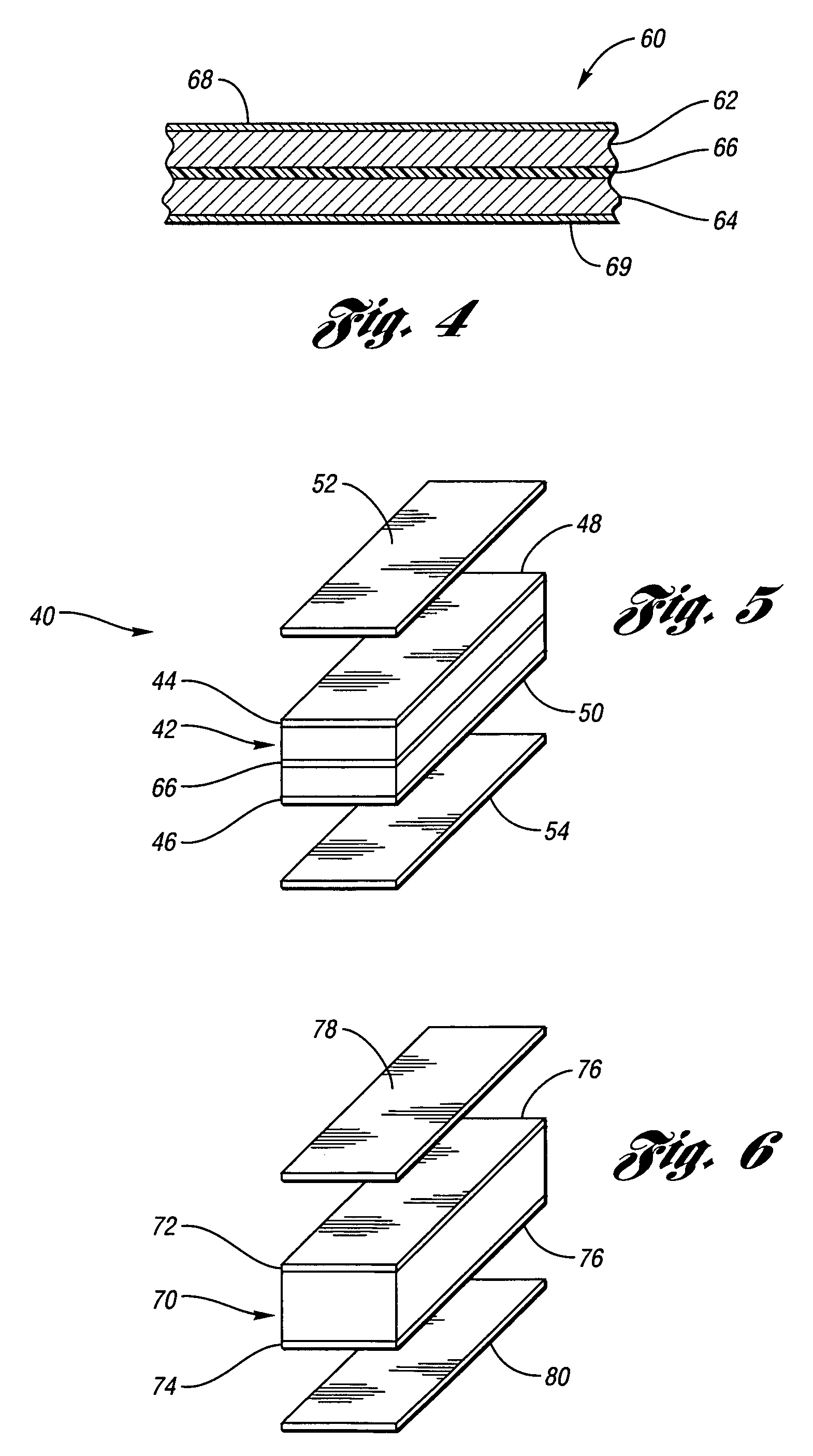
[0019]FIG. 5 is an exploded perspective view of a clutch plate portion 40 formed in accordance with the present invention. Referring to FIG. 5, the clutch plate portion 40 has a plate body 42, having a first surface 44 and a second surface 46. A first layer of bonding material 48 is in contact with the first surface 44 of the plate body 42 and a second layer of bonding material 50 is in contact with the second surface 46. A first layer of friction material 52 is in contact with the first layer of bonding material 48. A second layer of friction material 54 is in contact with the second layer of bonding material 50. Each bonding layer bonds the respective friction layer to the respective surface of the plate body 42. The pressure plate portion 16 may also be constructed using the structure described above.

[0020]In a first embodiment of the invention, the plate body 42 is formed from a laminated sheet vibration damping structure 60, also known as a constrained layer viscoelastic materi...

second embodiment

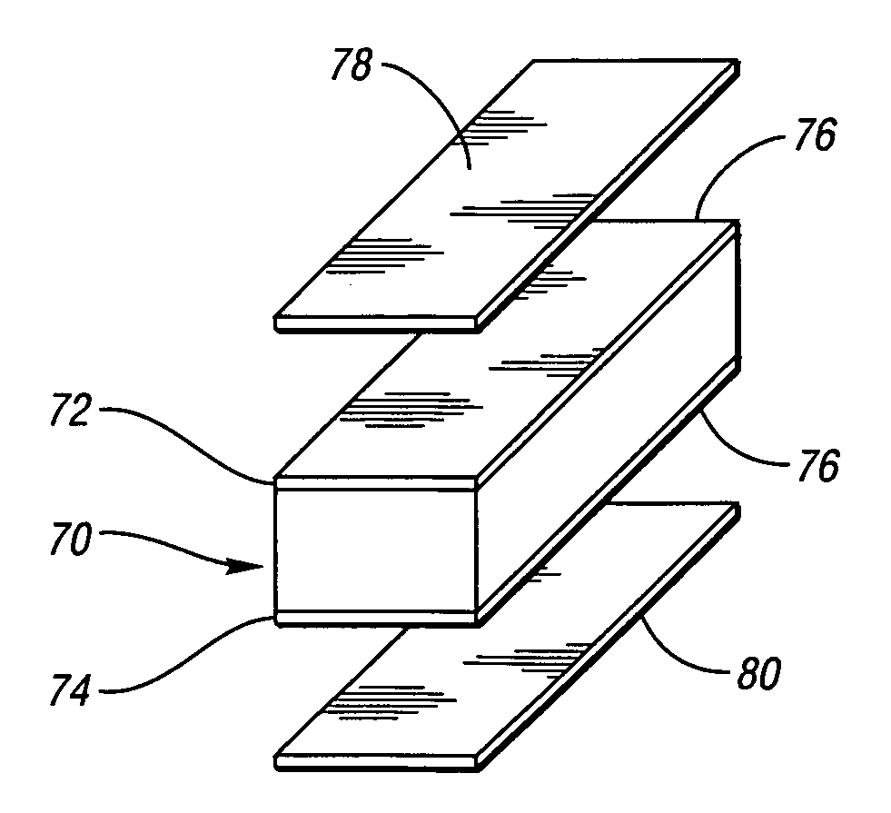
[0021]In the invention, as shown in FIG. 6, a plate body 70, with a first surface 72 and second surface 74, is configured for use on the clutch plate portion 14 or pressure plate portion 16. A first layer of bonding material is in contact with the first surface 72. A second layer of bonding material is in contact with the second surface 74. The bonding material used is an engineered viscoelastic material 76. The engineered viscoelastic material 76 is used to bond at least one layer of friction material 78 to the first surface 72. The engineered viscoelastic material 76 is used to bond at least one layer of friction material 80 to the second surface 74 of the plate body 70. The thickness of the viscoelastic material 76 is preferably 0.001″ to 0.005″. The viscoelastic material 76 has higher damping than ordinary adhesive such as phenolic resin, and will reduce vibrations and noise. The viscoelastic material 76 can be tuned to damp at different temperatures.

[0022]In a third embodiment ...


PUM

PropertyMeasurementUnit
thicknessaaaaaaaaaa
thicknessaaaaaaaaaa
thickaaaaaaaaaa

Abstract

The invention seeks to minimize the vibration and noise in a clutch plate system, by damping either or both the clutch plate and pressure plate with the use of various engineered viscoelastic materials. A clutch plate assembly is provided, comprising a plate body having a first surface and a second surface. In a first embodiment of the invention, the plate body is formed from a laminated sheet structure including two layers of steel having a viscoelastic core between the two layers and coextensive with the two layers. The viscoelastic core may be tunable to damp at different temperatures. In a second embodiment of the invention, an engineered viscoelastic material is used as a layer of bonding material for the first and second surface of the plate body. A method for damping a clutch plate assembly is provided.

Description

TECHNICAL FIELD[0001]The present invention relates to a damped clutch plate system, comprising a laminated steel structure with a viscoelastic layer designed for noise reduction and vibration damping.BACKGROUND OF THE INVENTION[0002]A clutch is typically used to connect or disconnect power from one functioning part of a vehicle to another. In a vehicle, a clutch is used to control transfer of engine power. The clutch disengages the engine and transmission as the gears are shifted and allows the engine to be operational when the wheels are stopped.[0003]A clutch typically comprises of a flywheel, clutch plate, pressure plate assembly and various linking mechanisms. Vibrations leading to noise, also known as shutter, occur when the clutch plate and the flywheel are spinning at different speeds with respect to each other. As the clutch plate and flywheel spin at different speeds, two or more components in the system couple together and begin to vibrate as a new system. In such cases, t...

Claims


Application Information

Patent Timeline
Patent Type & Authority Patents(United States)
IPC IPC(8): F16D13/64
CPCB32B15/08F16F9/306F16D13/60F16D13/64B32B15/18B32B2250/40B32B2255/06B32B2307/51B32B2307/538B32B2307/54B32B2307/714B32B2307/744B32B2307/752B32B2475/00B32B2605/00
Inventor LAZOWSKI, JEFFDENYS, ERIC
Owner MATERIALS SCI CORP
Why Eureka
Try Eureka